This chapter discusses the following topics:
Overview of an eight-node cluster (Section 12.1)
How to configure an eight-node cluster using an UltraSCSI BA356 and external termination (Section 12.2)
TruCluster Server Version 5.1B supports eight-member cluster configurations as follows:
Fibre Channel: Eight-member systems may be connected to common storage over Fibre Channel in a fabric (switch) configuration.
Parallel SCSI: Only four of the member systems may be connected to any one SCSI bus, but you can have multiple SCSI buses connected to different sets of nodes, and the sets of nodes may overlap. We recommend you use a DS-DWZZH-05 UltraSCSI hub with fair arbitration enabled when connecting four-member systems to a common SCSI bus using RAID array controllers.
Note
The DS-DWZZH-03/05 UltraSCSI hubs cannot be connected to a StorageWorks BA35X storage shelf because the storage shelf does not provide termination power to the hub.
Configuring an eight-member cluster using Fibre Channel is straightforward; connect the member systems to the Memory Channel hub and to the Fibre Channel switches. (See Chapter 7 for more information on configuring Fibre Channel).
Configuring an eight-member cluster using shared buses is more complex because you can only have four member systems on a single shared bus.
The primary focus of this chapter is on an eight-node cluster that uses externally terminated shared buses with minimal storage. This type of cluster is of primary interest to high-performance technical computing (HPTC) cluster customers. It is also of importance to those customers who use Tru64 UNIX Versions 4.0F or 4.0G with the TruCluster Software Products Memory Channel Software Version 1.6 product who want to upgrade to Tru64 UNIX Version 5.1B and TruCluster Server Version 5.1B.
Note
We do not expect customers upgrading from Tru64 UNIX Version 4.0F or 4.0G to also change their cluster interconnect from Memory Channel to private LAN.
12.1 Overview of an Eight-Node TruCluster Server Cluster
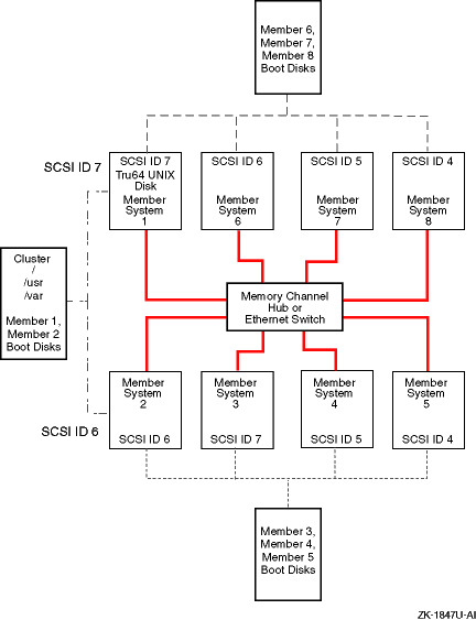
Figure 12-1 shows a basic block diagram of an eight-node cluster.
Note
The public network is not shown in Figure 12-1, or in any other illustration in this chapter. Ensure that you have network adapters for your public network.
This is just one of many ways to configure an eight-node cluster. You must choose a configuration that best fits your applications and needs.
Figure 12-1: Block Diagram of an Eight-Node Cluster
Figure 12-1 shows the following:
All member systems are connected via the cluster interconnect:
Memory Channel at the Memory Channel hub
Private LAN at the Ethernet switch
Three shared buses for shared storage.
Member systems 1 and 2 are on the first shared bus.
The Tru64 UNIX Version 5.1B operating system is installed on member system 1. It can be installed on an internal disk, as is the case in Figure 12-1, or on a shared disk.
Member system 1 is used to create the cluster with the
clu_create
command.
Member system 2 is added to the cluster with the
clu_add_member
command.
The shared storage for member systems 1 and 2 contains the
cluster root (/),
/usr,
/var
file systems, and the boot disks for
member systems 1 and 2.
(See the Tru64 UNIX
Installation Guide
and the TruCluster Server
Cluster Installation
manual for
information about installing the Tru64 UNIX and TruCluster Server
software.)
Give member systems 1 and 2 one vote.
Member systems 2, 3, 4, and 5 share storage on the second shared bus. Four systems is the maximum number of cluster members that may be on a shared bus.
The shared storage on this bus contains the member system boot disks for member systems 3, 4, and 5.
Use member system 1 or 2 to add member systems 3, 4, and 5 to the cluster.
Give member system 3 one vote.
Member Systems 1, 6, 7, and 8 form the third shared SCSI bus.
The shared storage on this bus contains the member system boot disks for member systems 6, 7, and 8.
Use member system 1 or 2 to add member systems 6, 7, and 8 to the cluster.
Section 12.2.1 and Figure 12-2 provide the details about cabling member systems 1 and 2 for the first shared bus.
Section 12.2.2 and Figure 12-3 provide the details about cabling the second shared bus and member systems 2, 3, 4, and 5 into the cluster.
Section 12.2.3 and Figure 12-4 provide the details about cabling the third shared bus and member systems 1, 6, 7, and 8 into the cluster.
Note
You can install Tru64 UNIX and TruCluster Server Version 5.1B after you complete member system 1 and 2 hardware installation, or you can wait until the hardware for all the systems is installed.
12.2 Configuring an Eight-Node Cluster Using an UltraSCSI BA356 and External Termination
Configuring an eight-node cluster is carried out in three distinct stages, one stage for each shared bus:
Install member systems 1 and 2 and all associated cluster hardware needed to place these two systems on a shared bus.
Install member systems 3, 4, and 5 and all associated cluster hardware needed to place these two systems on a shared SCSI bus with member system 2.
Install member systems 6, 7, and 8 and all associated cluster hardware needed to place these two systems on a shared SCSI bus with member system 1.
Note
You can switch steps 2 and 3 around and install member systems 6, 7, and 8 before member systems 3, 4, and 5.
12.2.1 Cabling the First Two Nodes on the First Externally Terminated Shared SCSI Cluster
This section provides installation instructions for the cluster hardware for the first two nodes of an eight-node shared bus cluster. Complete the steps in order. When you are referred to another section or table, complete those steps completely before returning to this section.
Notes
If you are upgrading from Tru64 UNIX Version 4.0F or V4.0G and TruCluster Memory Channel Software Version 1.6 to Tru64 UNIX Version 5.1B and TruCluster Server Version 5.1B, you are required to have shared storage, but you do not have to change your Memory Channel or public network hardware. Therefore, you can skip those steps except as follows.
If you are using the Memory Channel adapters in multiple-active rail mode with the TruCluster Memory Channel Software product, after you have installed the Tru64 UNIX and TruCluster Server Version 5.1B software, you will have to reset the
rmkernel subsystem configurationrm_rail_stylevariable to zero. The default forrm_rail_stylefor TruCluster Server Version 5.1B is 1, which enables failover pair. See the Cluster Highly Available Applications manual for more information.
Figure 12-2 provides a detailed illustration of the first two systems in an 8-node shared SCSI cluster. Table 12-1 lists the components that are used to create the portion of the cluster that is shown in Figure 12-2.
To install the cluster hardware for the first two member systems of an eight-node cluster, follow these steps:
Install the adapters for the cluster interconnect (Memory Channel adapters or Ethernet adapters for the private LAN) on member systems 1 and 2.
See Chapter 5 for installation and jumper information on the Memory Channel adapters. Delay testing the Memory Channel until you have installed all hardware.
See Chapter 6 for information on private LAN configuration.
Install a Memory Channel hub within 10 meters (32.8 feet) of all eight member systems.
Install the Ethernet switch within 25 meters (82 feet) of all eight member systems. The 25-meter (82-foot) limit for the private LAN is dictated by the maximum length of the SCSI cables.
Use BN39B-04 (4 meters; 13.1 feet) or BN39B-10 (10 meters; 32.8 feet) to connect the Memory Channel adapters of member systems 1 and 2 to the Memory Channel hub, or supported Ethernet cables to connect the private LAN Ethernet adapters to the Ethernet switch.
Install the network adapters for the public network on member systems 1 and 2. The public network is not shown in the illustrations in this chapter.
Refer to Table 10-2 and install two KZPBA host bus adapters on member system 1 and 2 for the shared buses that they will use:
A shared bus for member system 1 and 2
A shared bus for member system 2 with member systems 3, 4, and 5
A shared bus for member system 1 with member systems 5, 6, and 7
Ensure that you set the host bus adapter SCSI IDs as follows:
Member system 1: SCSI bus ID 7 (for both host bus adapters)
Member system 2: SCSI bus ID 6 (for both host bus adapters)
Ensure that each system (member system 1 and 2) has a BN21W-0B Y cable attached to each KZPBA host bus adapter and an H879-AA HD68 terminator attached to one leg of each BN21W-0B Y cable. Member systems 1 and 2 will be at one end of each of the two SCSI buses they share.
Prepare the UltraSCSI BA356 for TruCluster Server use. (See Section 11.4.1.3.) Ensure that you have installed an H8861-AA VHDCI trilink connector on the UltraSCSI BA356 personality module.
Note
If you need more storage than one UltraSCSI BA356 provides, you can daisy-chain two of them together. See Section 11.4.3.3 for more information.
Select one KZPBA host bus adapter on each system. Connect a BN38C, BN38D, or a combination of a BN38E-0B technology adapter cable and a BN37A cable between the open leg of the BN21W-0B Y cable on each system to the H8861-AA VHDCI trilink connector on the UltraSCSI BA356 personality module. This creates the shared bus between member systems 1 and 2.
The remaining KZPBA on each system has an open leg on its BN21W-0B Y cable. These connections will be used for the other shared buses.
Figure 12-2: First Two Nodes of an Eight-Node Cluster
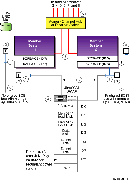
Table 12-1: Hardware Components Used for Configuration Shown in Figure 12-2
| Callout Number | Description |
| 1 | BN21W-0B HD68 Y cable |
| 2 | H879-AA HD68 terminator |
| 3 | BN38C or BN38D HD68 to VHDCI cable [Footnote 72] [Footnote 73] |
| 4 | H8861-AA VHDCI trilink connector |
| 5 | BN39B-04 or BN39B-10 Memory Channel cable or Ethernet cable |
| 6 | BN21K, BN21L, BN31G, or 328215-00X HD68 to HD68 cable |
If you have performed each step correctly, each of the first two member systems is prepared to be added to three other member systems on a shared bus.
You can install Tru64 UNIX and TruCluster Server Version 5.1B software at this time, or you can wait until all cluster hardware is installed.
You need to configure two four-node shared buses to create
your eight-node shared SCSI cluster.
The next two sections cover the
steps needed to configure member systems 3, 4, and 5 on
a shared bus with member system 2, and member systems 6, 7,
and 8 on a shared bus with member system 1.
12.2.2 Cabling the Second Externally Terminated Shared SCSI Bus
So far, you have configured a two-node externally terminated shared bus made up of member systems 1 and 2. This section covers the steps needed to configure member systems 3, 4, and 5 on a shared bus with member system 2.
Figure 12-3 shows a detailed illustration of member systems 2, 3, 4, and 5 on the second shared bus. Table 12-2 shows the components needed to configure the systems shown in Figure 12-3 into the cluster.
To configure member systems 2, 3, 4, and 5 on the second four-node shared bus, follow these steps:
Install the adapters for the cluster interconnect (Memory Channel adapters or Ethernet adapters for the private LAN) on member systems 3, 4, and 5.
See Chapter 5 for installation and jumper information on the Memory Channel adapters. Delay testing the Memory Channel until you have installed all hardware.
Note
If member systems 1 and 2 are running cluster software, do not run
mc_cableMemory Channel diagnostics. Shut all systems down to the console level to run themc_cablediagnostic.
See Chapter 6 for information on private LAN configuration.
Use BN39B-04 (4 meters; 13.1 feet) or BN39B-10 (10 meters; 32.8 feet) to connect the Memory Channel adapters of member systems 3, 4, and 5 to the Memory Channel hub, or Ethernet cables to connect the private LAN Ethernet adapters to the Ethernet switch.
Install the network adapters for the public network on member systems 3, 4, and 5. The public network is not shown in the illustrations in this chapter.
Referring to Table 10-2, install a KZPBA host bus adapter on member systems 3, 4, and 5. These host bus adapters will be used to form a shared SCSI bus with member system 2.
Ensure that you set the host bus adapter SCSI IDs as follows:
Member system 2: SCSI ID 6 (which was set earlier)
Member system 3: SCSI ID 7
Member system 4: SCSI ID 5
Member system 5: SCSI ID 4
Ensure that each system (member system 3, 4, and 5) has a BN21W-0B Y cable attached to the KZPBA host bus adapter.
Ensure that there is an H879-AA terminator attached to one leg of the BN21W-0B on member system 5. Member systems 2 and 5 will be at the end of this shared bus.
Prepare the UltraSCSI BA356 for TruCluster Server use (see Section 11.4.1.3). Ensure that you have installed an H8861-AA VHDCI trilink connector on the UltraSCSI BA356 personality module.
Note
If you need more storage than one UltraSCSI BA356 provides, you can daisy-chain two of them together. See Section 11.4.3.3 for more information.
Connect a BN21K, BN21L, BN31G, or 328215-00X cable between the BN21W-0B Y cables on member system 2 and member system 3.
Connect a BN21K, BN21L, BN31G, or 328215-00X cable between the BN21W-0B Y cables on member system 4 and member system 5.
Connect a BN38C, BN38D, or a combination of a BN38E-0B technology adapter cable and a BN37A cable between the open leg of the BN21W-0B on member systems 3 and 4 to the H8861-AA VHDCI trilink connector on the UltraSCSI BA356 personality module.
Figure 12-3: Second Shared SCSI Bus of an Eight-Node Cluster
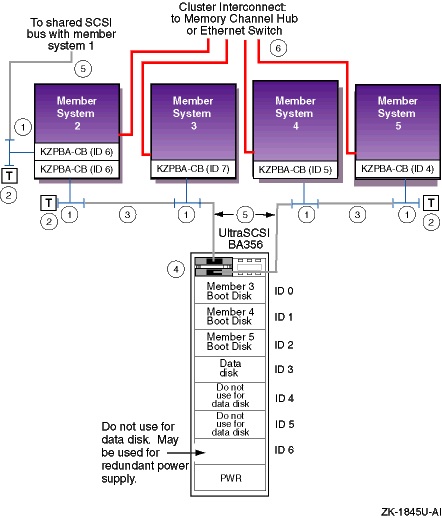
Table 12-2
lists the components that
are used to create the cluster shown in
Figure 12-3.
Table 12-2: Hardware Components Used for Configuration Shown in Figure 12-3
| Callout Number | Description |
| 1 | BN21W-0B HD68 Y cable |
| 2 | H879-AA HD68 terminator |
| 3 | BN21K, BN21L, BN31G, or 328215-00X HD68 to HD68 cable [Footnote 74] |
| 4 | H8861-AA VHDCI trilink connector |
| 5 | BN38C or BN38D HD68 to VHDCI cable [Footnote 74] [Footnote 75] |
| 6 | BN39B-04 or BN39B-10 Memory Channel cable or Ethernet cable |
12.2.3 Cabling the Third Externally Terminated Shared SCSI Bus
So far, you have configured a two-node externally terminated shared bus made up of member systems 1 and 2, and an externally terminated four-node shared bus with member systems 2, 3, 4, and 5. You need to configure a third externally terminated four-node shared bus to complete your eight-node shared SCSI cluster.
This section covers the steps needed to configure member systems 1, 6, 7, and 8 on an externally terminated shared bus.
Figure 12-4 shows a detailed illustration of member systems 1, 6, 7, and 8 on a shared bus. Table 12-3 lists the components needed to configure the systems shown in Figure 12-4.
To configure member systems 1, 6, 7, and 8 on a four-node shared SCSI bus, follow these steps:
Install the adapters for the cluster interconnect (Memory Channel adapters or Ethernet adapters for the private LAN) on member systems 6, 7, and 8.
See Chapter 5 for installation and jumper information on the Memory Channel adapters. Delay testing the Memory Channel until you have installed all hardware.
Note
If member systems 1 and 2 are running cluster software, do not run
mc_cableMemory Channel diagnostics. Shut all systems down to the console level to run themc_cablediagnostic.
See Chapter 6 for information on private LAN configuration.
Use BN39B-04 (4 meters; 13.1 feet) or BN39B-10 (10 meters; 32.8 feet) to connect the Memory Channel adapters of member systems 6, 7, and 8 to the Memory Channel hub, or Ethernet cables to connect the private LAN Ethernet adapters to the Ethernet switch.
Refer to the hardware manuals and install the network adapters for the public network on member systems 6, 7, and 8. The public network is not shown in the illustrations in this chapter.
Referring to Table 10-2, install a KZPBA host bus adapter on member system 6, 7, and 8. These host bus adapters will be used to form a shared SCSI bus with member system 1.
Ensure that you set the host bus adapter SCSI IDs as follows:
Member system 1: SCSI bus ID 7 (which was set earlier)
Member system 6: SCSI bus ID 6
Member system 7: SCSI bus ID 5
Member system 8: SCSI bus ID 4
Ensure that each system (member system 6, 7, and 8) has a BN21W-0B Y cable attached to the KZPBA host bus adapter.
Ensure that there is an H879-AA terminator attached to one leg of the BN21W-0B on member system 8. Member systems 1 and 8 will be at the end of this shared bus.
Prepare the UltraSCSI BA356 for TruCluster Server use. (See Section 11.4.1.3.) Ensure that you have installed an H8861-AA VHDCI trilink connector on the UltraSCSI BA356 personality module.
Note
If you need more storage than one UltraSCSI BA356 provides, you can daisy-chain two of them together. See Section 11.4.3.3 for more information.
Connect a BN21K, BN21L, BN31G, or 328215-00X cable between the BN21W-0B Y cables on member system 1 and member system 6.
Connect a BN21K, BN21L, BN31G, or 328215-00X cable between the BN21W-0B Y cables on member system 7 and member system 8.
Connect a BN38C, BN38D, or a combination of a BN38E-0B technology adapter cable and a BN37A cable between the open leg of the BN21W-0B on member systems 6 and 7 to the H8861-AA VHDCI trilink connector on the UltraSCSI BA356 personality module.
Figure 12-4: Third Shared SCSI Bus of an Eight-Node Cluster
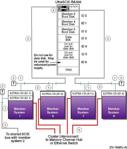
Table 12-3
lists the components that
are used to create the cluster shown in
Figure 12-4.
Table 12-3: Hardware Components Used for Configuration Shown in Figure 12-4
| Callout Number | Description |
| 1 | BN21W-0B HD68 Y cable |
| 2 | H879-AA HD68 terminator |
| 3 | BN21K, BN21L, BN31G, or 328215-00X HD68 to HD68 cable |
| 4 | H8861-AA VHDCI trilink connector |
| 5 | BN38C or BN38D HD68 to VHDCI cable [Footnote 76] [Footnote 77] |
| 6 | BN39B-04 or BN39B-10 Memory Channel cable or Ethernet cable |