This chapter provides an overview of Fibre Channel, Fibre Channel configuration examples, and information on Fibre Channel hardware installation and configuration in a Tru64 UNIX or TruCluster Server Version 5.1B configuration.
This chapter discusses the following topics:
Overview of Fibre Channel (Section 7.1)
Comparison of Fibre Channel topologies (Section 7.2)
Example cluster configurations using Fibre Channel storage (Section 7.3)
Brief discussion of QuickLoop (Section 7.4)
Discussion of zoning (Section 7.5)
Discussion of cascaded switches (Section 7.6)
Procedure for Tru64 UNIX Version 5.1B or TruCluster Server Version 5.1B installation using Fibre Channel disks (Section 7.7)
Steps necessary to install and configure the Fibre Channel hardware (Section 7.8)
The initial steps for setting up storage (Section 7.9)
Steps necessary to install the base operating system and cluster software using disks accessible over the Fibre Channel hardware (Section 7.10)
How to convert the HSG80 from transparent to multiple-bus failover mode (Section 7.11)
Using the Storage System Scripting Utility (Section 7.12)
Discussion on how you can use the
emx
manager (emxmgr) to display the presence of Fibre
Channel adapters, target ID mappings for a Fibre Channel adapter, and
the current Fibre Channel topology (Section 7.13)
The information includes an example storageset configuration, how
to determine the
/dev/disk/dskn
value that corresponds to the Fibre Channel storagesets that have
been set up as the Tru64 UNIX boot disk, cluster root
(/), cluster
/usr,
cluster
/var, cluster member boot, and
quorum disks, and how to set up the
bootdef_dev
console environment
variable to facilitate Tru64 UNIX Version 5.1B and TruCluster Server
Version 5.1B installation.
Note
TruCluster Server Version 5.1B configurations require one or more disks to hold the Tru64 UNIX operating system. The disks are either private disks on the system that will become the first cluster member, or disks on a shared bus that the system can access.
Whether or not you install the base operating system on a shared disk, always shut down the cluster before booting the Tru64 UNIX disk.
TruCluster Server requires a cluster interconnect, which can be the Memory Channel, or a private LAN. (See Chapter 6 for more information on the LAN interconnect.)
Fibre Channel supports multiple protocols over the same physical interface. Fibre Channel is primarily a protocol-independent transport medium; therefore, it is independent of the function for which you use it.
TruCluster Server uses the Fibre Channel Protocol (FCP) for SCSI to use Fibre Channel as the physical interface.
Fibre Channel, with its serial transmission method, overcomes the limitations of parallel SCSI by providing:
Support for multiple protocols
Better scalability
Improved reliability, serviceability, and availability
Fibre Channel uses an extremely high-transmit clock frequency to
achieve the high data rate.
Using optical fiber transmission lines
allows the high-frequency information to be sent up to
40 kilometers (24.85 miles), which is the maximum distance between
transmitter and receiver.
Copper transmission lines may be used for
shorter distances.
7.1.1 Basic Fibre Channel Terminology
The following list describes the basic Fibre Channel terminology:
The Arbitrated Loop Physical Address (AL_PA) is used to address nodes on the Fibre Channel loop. When a node is ready to transmit data, it transmits Fibre Channel primitive signals that include its own identifying AL_PA.
A Fibre Channel topology in which frames are routed around a loop set up by the links between the nodes in the loop. All nodes in a loop share the bandwidth, and bandwidth degrades slightly as nodes and cables are added.
All data is transferred in a packet of information called a frame. A frame is limited to 2112 bytes. If the information consists of more than 2112 bytes, it is divided up into multiple frames.
The source and destination of a frame. A node may be a computer system, a redundant array of independent disks (RAID) array controller, or a disk device. Each node has a 64-bit unique node name (worldwide name) that is built into the node when it is manufactured.
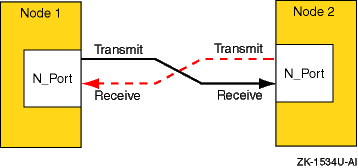
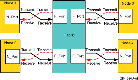
Each node must have at least one Fibre Channel port from which to send or receive data. This node port is called an N_Port. Each port is assigned a 64-bit unique port name (worldwide name) when it is manufactured. An N_Port is connected directly to another N_Port in a point-to-point topology. An N_Port is connected to an F_Port in a fabric topology.
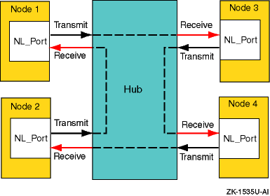
In an arbitrated loop topology, information is routed around a loop. A node port that can operate on the loop is called an NL_Port (node loop port). The information is repeated by each NL_Port until it reaches its destination. Each port has a 64-bit unique port name (worldwide name) that is built into the node when it is manufactured.
A switch, or multiple interconnected switches, that route frames between the originator node (transmitter) and destination node (receiver).
The ports within the fabric (fabric port). This port is called an F_port. Each F_port is assigned a 64-bit unique node name and a 64-bit unique port name when it is manufactured. Together, the node name and port name make up the worldwide name.
An F_Port containing the loop functionality is called an FL_Port.
The physical connection between an N_Port and another N_Port or an N_Port and an F_Port. A link consists of two connections, one to transmit information and one to receive information. The transmit connection on one node is the receive connection on the node at the other end of the link. A link may be optical fiber, coaxial cable, or shielded twisted pair.
An expansion port on a switch used to make a connection between two switches in the fabric.
7.1.2 Fibre Channel Topologies
Fibre Channel supports three different interconnect topologies:
Point-to-point (Section 7.1.2.1)
Fabric (Section 7.1.2.2)
Arbitrated loop (Section 7.1.2.3)
Note
Although you can interconnect an arbitrated loop with fabric, hybrid configurations are not supported at the present time, and therefore are not discussed in this manual.
The point-to-point topology is the simplest Fibre Channel topology. In a point-to-point topology, one N_Port is connected to another N_Port by a single link.
Because all frames transmitted by one N_Port are received by the other N_Port, and in the same order in which they were sent, frames require no routing.
Figure 7-1
shows an example point-to-point
topology.
Figure 7-1: Point-to-Point Topology
The fabric topology provides more connectivity than point-to-point topology. The fabric topology can connect up to 224 ports.
The fabric examines the destination address in the frame header and routes the frame to the destination node.
A fabric may consist of a single switch, or there may be several interconnected switches (up to three interconnected switches are supported). Each switch contains two or more fabric ports (F_Port) that are internally connected by the fabric switching function, which routes the frame from one F_Port to another F_Port within the switch. Communication between two switches is routed between two expansion ports (E_Ports).
When an N_Port is connected to an F_Port, the fabric is responsible for the assignment of the Fibre Channel address to the N_Port attached to the fabric. The fabric is also responsible for selecting the route a frame will take, within the fabric, to be delivered to the destination.
When the fabric consists of multiple switches, the fabric can determine an alternate route to ensure that a frame gets delivered to its destination.
Figure 7-2
shows an example fabric topology.
Figure 7-2: Fabric Topology
7.1.2.3 Arbitrated Loop Topology
In an arbitrated loop topology, frames are routed around a loop set up by the links between the nodes. The hub maintains loop continuity by bypassing a node when the node or its cabling fails, when the node is powered down, or when the node is removed for maintenance. The hub is transparent to the protocol. It does not consume any Fibre Channel arbitrated loop addresses so it is not addressable by a Fibre Channel arbitrated loop port.
The nodes arbitrate to gain control (become master) of the loop. After a node becomes master, the nodes select (by way of setting bits in a bitmask) their own Arbitrated Loop Physical Address (AL_PA). The AL_PA is used to address nodes on the loop. The AL_PA is dynamic and can change each time the loop is initialized, a node is added or removed, or at any other time that an event causes the membership of the loop to change. When a node is ready to transmit data, it transmits Fibre Channel primitive signals that include its own identifying AL_PA.
In the arbitrated loop topology, a node port is called an NL_Port (node loop port), and a fabric port is called an FL_Port (fabric loop port).
Figure 7-3
shows an example of an arbitrated
loop topology.
Figure 7-3: Arbitrated Loop Topology
7.2 Fibre Channel Topology Comparison
This section compares and contrasts the fabric and arbitrated loop topologies and describes why you might choose to use them.
When compared with the fabric (switched) topology, arbitrated loop is a lower cost, and lower performance, alternative. Arbitrated loop reduces Fibre Channel cost by substituting a lower-cost, often nonintelligent and unmanaged hub, for a more expensive switch. The hub operates by collapsing the physical loop into a logical star. The cables, associated connectors, and allowable cable lengths are similar to those of a fabric. Arbitrated loop supports a theoretical limit of 127 nodes in a loop. Arbitrated loop nodes are self-configuring and do not require Fibre Channel address switches.
Arbitrated loop provides reduced cost at the expense of bandwidth; all nodes in a loop share the bandwidth, and bandwidth degrades slightly as nodes and cables are added. Nodes on the loop see all traffic on the loop, including traffic between other nodes. The hub can include port-bypass functions that manage movement of nodes on and off the loop. For example, if the port bypass logic detects a problem, the hub can remove that node from the loop without intervention. Data availability is then preserved by preventing the down time associated with node failures, cable disconnections, and network reconfigurations. However, traffic caused by node insertion and removal, errors, and so forth, can cause temporary disruption on the loop.
Although the fabric topology is more expensive, it provides both increased connectivity and higher performance; switches provide a full-duplex 1 Gb or 2 Gb/sec point-to-point connection to the fabric. Switches also provide improved performance and scaling because nodes on the fabric see only data destined for themselves, and individual nodes are isolated from reconfiguration and error recovery of other nodes within the fabric. Switches can provide management information about the overall structure of the Fibre Channel fabric, which may not be the case for an arbitrated loop hub.
Table 7-1
compares the fabric and
arbitrated loop topologies.
Table 7-1: Fibre Channel Fabric and Arbitrated Loop Comparison
| When to Use Arbitrated Loop | When to Use Fabric |
| In clusters of two members | In clusters of more than two members |
| In applications where low total solution cost and simplicity are key requirements | In multinode cluster configurations when possible temporary traffic disruption due to reconfiguration or repair is a concern |
| In applications where the shared bandwidth of an arbitrated loop configuration is not a limiting factor | In high bandwidth applications where a shared arbitrated loop topology is not adequate |
| In configurations where expansion and scaling are not anticipated | In cluster configurations where expansion is anticipated and requires performance scaling |
7.3 Example Fibre Channel Configurations Supported by TruCluster Server
This section provides diagrams of some of the configurations supported
by TruCluster Server Version 5.1B.
Diagrams are provided for both
transparent failover mode and multiple-bus failover mode.
7.3.1 Fibre Channel Cluster Configurations for Transparent Failover Mode
With transparent failover mode:
The hosts do not know a failover has taken place (failover is transparent to the hosts).
The units are divided between an HSG80 port 1 and port 2.
If there are dual-redundant HSG80 controllers, controller A port 1 and controller B port 2 are normally active; controller A port 2 and controller B port 1 are normally passive.
If one controller fails, the other controller takes control and both its ports are active.
Figure 7-4
shows a typical Fibre Channel
cluster configuration using transparent failover mode.
Figure 7-4: Fibre Channel Single Switch Transparent Failover Configuration
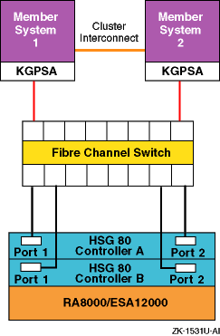
In transparent failover, units D00 through D99 are accessed through port 1 of both controllers. Units D100 through D199 are accessed through port 2 of both HSG80 controllers.
You cannot achieve a no-single-point-of-failure (NSPOF) configuration using transparent failover. The host cannot initiate failover, and if you lose a host bus adapter, switch or hub, or a cable, you lose the units behind at least one port.
You can, however, add the hardware for a second bus (another KGPSA, switch, and RA8000/ESA12000 with associated cabling) and use LSM to mirror across the buses. However, because you cannot use LSM to mirror the member boot partitions or the quorum disk you cannot obtain an NSPOF transparent failover configuration, even though you have increased availability.
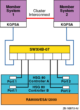
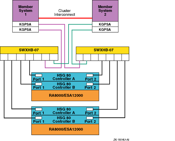
Figure 7-5
shows a two-node Fibre Channel
cluster with a single RA8000 or ESA12000 storage array with
dual-redundant HSG80 controllers and an DS-SWXHB-07 Fibre Channel hub.
Figure 7-5: Arbitrated Loop Configuration with One Storage Array
7.3.2 Fibre Channel Cluster Configurations for Multiple-Bus Failover Mode
With multiple-bus failover:
The host controls the failover by accessing units over a different path or causing the access to the unit to be through the other HSG80 controller.
An active controller causes a failover to the other controller if the controller recognizes the loss of the switch, hub, or cable to a controller port.
Each cluster member system has two or more (fabric only) KGPSA host bus adapters (multiple paths to the storage units).
Normally, all available units (D0 through D199) are available at all host ports. Only one HSG80 controller will be actively doing I/O for any particular storage unit.
However, both controllers can be forced active by preferring units to one
controller or the other (SET
unit
PREFERRED_PATH=THIS).
By balancing the preferred units, you
can obtain the best I/O performance using two controllers.
Note
If you have preferred units, and the HSG80 controllers restart because of an error condition or power failure, and one controller restarts before the other controller, the HSG80 controller restarting first will take all the units, whether they are preferred or not. When the other HSG80 controller starts, it will not have access to the preferred units, and will be inactive.
Therefore, you want to ensure that both HSG80 controllers start at the same time under all circumstances so that the controller sees its own preferred units.
Figure 7-6 and Figure 7-7 show two different recommended multiple-bus NSPOF cluster configurations. The only difference is the fiber-optic cable connection path between the switch and the HSG80 controller ports.
There is no difference in performance between these two configurations. It may be easier to cable the configuration shown in Figure 7-6 because the cables from one switch (or switch zone) both go to the ports on the same side of both controllers (for example, port 1 of both controllers).
Figure 7-6: Multiple-Bus NSPOF Configuration Number 1
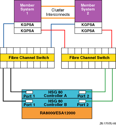
Figure 7-7: Multiple-Bus NSPOF Configuration Number 2
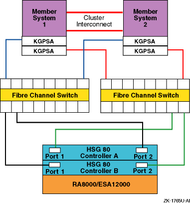
The configuration that is shown in Figure 7-8 is an NSPOF configuration, but is not a recommended cluster configuration because of the performance loss during failure conditions. If a switch or cable failure causes a failover to the other switch, access to the storage units has to be moved to the other controller, and that takes time. In the configurations shown in Figure 7-6 and Figure 7-7, the failure would cause access to the storage unit to shift to the other port of the same controller. This is faster than a change of controllers, providing better overall performance.
Note
If you have a configuration like the one that is shown in Figure 7-8, change the switch to HSG80 cabling to match the configurations that are shown in Figure 7-6 or Figure 7-7.
The single-system configuration that is shown in
Figure 7-9
is also a configuration that we do not
recommend.
Figure 7-8: Configuration That Is Not Recommended
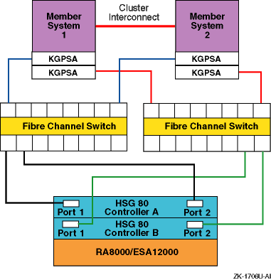
Figure 7-9: Another Configuration That Is Not Recommended
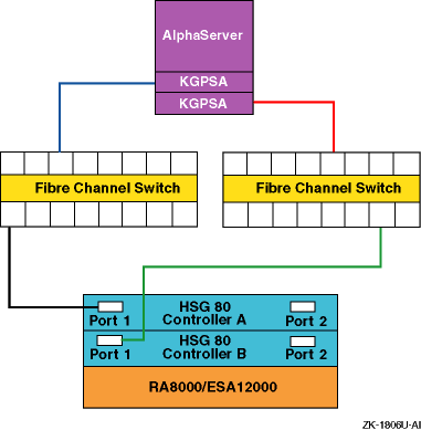
Figure 7-10
shows the maximum
supported arbitrated loop configuration of a two-node Fibre Channel
cluster with two RA8000 or ESA12000 storage arrays, each with
dual-redundant HSG80 controllers and two DS-SWXHB-07 Fibre Channel hubs.
This provides an NSPOF configuration.
Figure 7-10: Arbitrated Loop Maximum Configuration
QuickLoop supports Fibre Channel arbitrated loop (FC-AL) devices within a fabric. This logical private loop fabric attach (PLFA) consists of multiple private arbitrated loops (looplets) that are interconnected by a fabric. A private loop is formed by logically connecting ports on up to two switches.
Note
QuickLoop is not supported in a Tru64 UNIX Version 5.1B configuration or TruCluster Server Version 5.1B configuration.
This section provides a brief overview of zoning.
A zone is a logical subset of the Fibre Channel devices that are connected to the fabric. Zoning allows partitioning of resources for management and access control. In some configurations, it may provide for more efficient use of hardware resources by allowing one switch to serve multiple clusters or even multiple operating systems. Zoning entails splitting the fabric into zones, where each zone is essentially a virtual fabric.
Zoning may be used:
When you want to set up barriers between systems of different operating environments or uses, for instance to allow two clusters to utilize the same switch.
To create test areas that are separate from the rest of the fabric.
To provide better utilization of a switch by reducing the number of unused ports.
Note
Any initial zoning must be made before connecting the host bus adapters and the storage to the switches, but after zoning is configured, changes can be made dynamically.
7.5.1 Switch Zoning Versus Selective Storage Presentation
Switch zoning and the selective storage presentation (SSP) feature of the HSG80 controllers have similar functions.
Switch zoning controls which servers can communicate with each other and each storage controller host port. SSP controls which servers will have access to each storage unit.
Switch zoning controls access at the storage system level, whereas SSP controls access at the storage unit level.
The following configurations require zoning or selective storage presentation:
When you have a TruCluster Server cluster in a storage array network (SAN) with other standalone systems (UNIX or non-UNIX), or other clusters.
Any time you have Windows NT or Windows 2000 in the same SAN with Tru64 UNIX. (Windows NT or Windows 2000 must be in a separate switch zone.)
The SAN configuration has more than 64 connections to an RA8000, ESA12000, MA6000, MA8000, or EMA12000.
The use of selective storage presentation is the preferred way to
control access to storage (so zoning is not required).
7.5.2 Types of Zoning
There are two types of zoning, soft and hard:
Soft zoning is a software implementation that is based on the Simple Name Server (SNS) enforcing a zone. Zones are defined by either the node or port World Wide Names (WWN), or the domain and port numbers in the form of D,P, where D is the domain and P is the physical port number on the switch.
A host system requests a list of all adapters and storage controllers that are connected to the fabric. The name service provides a list of all ports that are in the same zone or zones as the requesting host bus adapter.
Soft zoning only works if all hosts honor it; it does not work if a host is not programmed to allow for soft zoning. For instance, if a host tries to access a controller that is outside the zone, the switch does not prevent the access.
Tru64 UNIX honors soft zoning and does not attempt to access devices outside the zone.
If you have used the WWN to define the zone and replace a KGPSA host bus adapter, you must modify the zone configuration and SSP because the node World Wide Name has changed.
With hard zoning, zones are enforced at the physical level across all fabric switches by hardware blocking of Fibre Channel frames. Hardware zone definitions are in the form of D,P, where D is the domain and P is the physical port number on the switch. An example might be 1,2 for switch 1, port 2.
If a host attempts to access a port that is outside its zone, the switch hardware blocks the access.
You must modify the zone configuration when you move any cables from one port to another within the zone.
If you want to guarantee that there is no access outside any zone, either use hard zoning, or use operating systems that state that they support soft zoning.
Table 7-2
lists the
types of zoning that are supported on each of the supported Fibre
Channel switches.
Table 7-2: Type of Zoning Supported by Switches
| Switch Type | Type of Zoning Supported |
| DS-DSGGA | Soft |
| DS-DSGGB | Soft and Hard |
| DS-DSGGC | Soft and Hard |
Figure 7-11
provides an example configuration using
zoning.
This configuration consists of two
independent zones with each zone containing an independent cluster.
Figure 7-11: Simple Zoned Configuration
For information on setting up zoning, see the SAN Switch Zoning
documentation that is provided with the switch.
7.6 Cascaded Switches
Multiple switches may be connected to each other to form a network of switches, or cascaded switches.
A cascaded switch configuration, which allows for network failures
up to and including the switch without losing a data path to a
SAN connected node, is called a mesh or meshed fabric.
Figure 7-12
shows an example meshed fabric with
three cascaded switches.
This is not a
no-single-point-of-failure (NSPOF) configuration.
Figure 7-12: Meshed Fabric with Three Cascaded Switches
Figure 7-13
shows an example meshed
resilient fabric with four cascaded interconnected switches.
This configuration will tolerate multiple data path failures, and
is an NSPOF configuration.
Figure 7-13: Meshed Resilient Fabric with Four Cascaded Switches
Note
If you lose an ISL, the communication can be routed through another switch to the same port on the other controller. This can constitute the maximum allowable two hops.
You can find the following information about storage array networks (SAN) in the Heterogeneous Open SAN Design Reference Guide located at:
http://www5.compaq.com/products/storageworks/techdoc/san/AA-RMPNA-TE.html
Supported SAN topologies
SAN fabric design rules
SAN platform and operating system restrictions (including the number of switches supported)
7.7 Procedure for Installation Using Fibre Channel Disks
Use the following procedure to install Tru64 UNIX Version 5.1B and TruCluster Server Version 5.1B using Fibre Channel disks. If you are only installing Tru64 UNIX Version 5.1B, complete the first eight steps. Complete all the steps for a TruCluster Server Version 5.1B installation. See the Tru64 UNIX Installation Guide, TruCluster Server Cluster Installation manual, and other hardware manuals as appropriate for the actual installation procedures.
Install the Fibre Channel switch or hub (Section 7.8.1 or Section 7.8.2).
Install the Fibre Channel host bus adapters (Section 7.8.3).
Set up the HSG80 RAID array controllers for a fabric or loop configuration (Section 7.9.1).
Configure the HSG80 or Enterprise Virtual Array disks to be used for installation of the base operating system and cluster. Be sure to set the identifier for each storage unit you will use for operating system or cluster installation (Section 7.9.1.4.1 and Section 7.9.1.4.2).
If the system is not already powered on, power on the system where you will install Tru64 UNIX Version 5.1B. If this is a cluster installation, this system will also be the first cluster member.
Use the console WWID manager (wwidmgr) utility to set the
device unit number for the Fibre Channel Tru64 UNIX Version 5.1B disk and first
cluster member system boot disk (Section 7.10.1).
Use the
show wwid*
and
show
n*
console commands to show the disk devices that are
currently reachable, and the paths to the devices (Section 7.10.2).
See the Tru64 UNIX Installation Guide and install the base operating system from the CD-ROM. The installation procedure will recognize the disks for which you set the device unit number. Select the disk that you have chosen as the Tru64 UNIX operating system installation disk from the list of disks that is provided (Section 7.10.3).
After the new kernel has booted to multi-user mode, complete the operating system installation.
If you will not be installing TruCluster Server software, reset the
bootdef_dev
console
environment variable to provide multiple boot paths to the
boot disk (Section 7.10.4), then boot the operating system.
Determine the
/dev/disk/dskn
values
to be used for cluster installation (Section 7.10.5).
Use the
disklabel
utility to label the disks
that were used to create the cluster (Section 7.10.6).
See the TruCluster Server
Cluster Installation
manual and
install the TruCluster Server software subsets, then run the
clu_create
command to create the first cluster
member.
Do not allow
clu_create
to boot the
system.
Shut down the system to the console prompt (Section 7.10.7).
Reset the
bootdef_dev
console
environment variable to provide multiple boot paths to the
cluster member boot disk (Section 7.10.4).
Boot the first cluster member.
See the Cluster Installation manual and add subsequent cluster member systems (Section 7.10.8). Like with the first cluster member, you will have to:
Use the
wwidmgr
command to set the
device unit number for the member system boot disk.
Set the
bootdef_dev
environment variable.
Reset the
bootdef_dev
environment variable after
building a kernel on the new cluster member system.
7.8 Installing and Configuring Fibre Channel Hardware
This section provides information about installing the Fibre Channel hardware that is needed to support Tru64 UNIX or a TruCluster Server configuration using Fibre Channel storage.
Ensure that the member systems, the Fibre Channel switches or hubs, and the HSG80 array controllers are placed within the lengths of the optical cables that you will be using.
Note
The maximum length of the optical cable between the KGPSA and the switch (or hub), or the switch (or hub) and the HSG80 array controller, is 500 meters (1640.4 feet) via shortwave multimode Fibre Channel cable. The maximum distance between switches in a cascaded switch configuration is 10 kilometers (6.2 miles) using longwave single-mode fiber.
7.8.1 Installing the Fibre Channel Switch
Install and set up your Fibre Channel switches. See the documentation that came with the switch.
Install a minimum of two Fibre Channel switches if you have plans for a no-single-point-of-failure (NSPOF) configuration.
All switches have a 10Base-T Ethernet (RJ45) port, and after the IP address is set, the Ethernet connection allows you to manage the switch:
Remotely using a telnet TCP/IP connection
With the Simple Network Management Protocol (SNMP)
If it is necessary to set up switch zoning, you can do so after
installing the Fibre Channel host bus adapters, storage hardware,
and associated cabling.
7.8.2 Installing and Setting Up the DS-SWXHB-07 Hub
The DS-SWXHB-07 hub supports up to seven 1.6025 Gb/sec ports. The ports can be connected to the DS-KGPSA-CA PCI-to-Fibre Channel host bus adapter or to an HSG80 array controller.
Unlike the DSGGA switch, the DS-SWXHB-07 hub does not have any controls or even a power-on switch. Simply plug in the hub to power it on. The hub has a green power indicator on the front panel.
The DS-SWXHB-07 hub has slots to accommodate up to seven plug-in interface converters. Each interface converter in turn supports two 1-gigabit Gigabit Interface Converter (GBIC) modules. The GBIC module is the electrical-to-optical converter, and supports both 50-micron and 62.5-micron multi-mode fiber (MMF) using the standard SC connector. Only the 50-micron MMF optical cable is supported for the TruCluster Server products.
The GBIC modules and MMF optical cables are not
provided with the hub.
To obtain them, contact your
authorized Service Representative.
7.8.2.1 Installing the Hub
Ensure that you place the hub within 500 meters (1640.4 feet) of the member systems (with DS-KGPSA-CA PCI-to-Fibre Channel adapter) and the HSG80 array controllers.
The DS-SWXHB-07 hub can be placed on a flat, solid surface or, when configured in the DS-SWXHX-07 rack mount kit, part number 242795-B21, the hub can be mounted in a 48.7-cm (19-in) rackmount installation. (One rack kit holds two hubs.) The hub is shipped with rubber feet to prevent marring the surface.
When you plan the hub location, ensure that you provide access to the GBIC connectors on the back of the hub. All cables plug into the back of the hub.
Caution
Static electricity can damage modules and electronic components. We recommend using a grounded antistatic wrist strap and a grounded work surface when handling modules.
For an installation, at a minimum, you have to:
Place the hub on an acceptable surface or install it in the rackmount.
Install one or more GBIC modules. Gently push the GBIC module into an available port on the hub until you feel the GBIC module click into place. The GBIC module has a built-in guide key that prevents you from inserting it incorrectly. Do not use excessive force.
Connect the optical fiber cables. To do this, plug one end of an MMF cable into one of the GBIC modules installed in the hub. Attach an MMF cable for all active port connections. Unused ports or improperly seated GBIC modules remain in loop bypass and do not affect the operation of the loop.
Attach the other end of the MMF cable to either the DS-KGPSA-CA adapter or to the HSG80.
Connect power to the hub using a properly grounded outlet. Look at the power indicator on the front of the hub to make sure that it powered on.
For more installation information, see the
Fibre Channel Storage Hub 7 Installation Guide.
7.8.2.2 Determining the Hub Status
Because the DS-SWXHB-07 hub is not a manageable unit, examine the status of the LED indicators to make sure that the hub is operating correctly. The LED indicators will be particularly useful after you have connected the hub to the DS-KGPSA-CA host adapters and the HSG80 controller. However, at this time you can use the LEDs to verify that the GBIC connectors are installed correctly.
At power on, with no optical cables attached, the green and amber LEDs should both be on, indicating that the port is active but that the connection is invalid. The other possible LED states are as follows:
Both off: Not active. Make sure that the GBIC is installed correctly.
Solid green: Indicates presence and proper functionality of a GBIC.
Green off: Indicates a fault condition (GBIC transmitter fault, improperly seated GBIC, no GBIC installed, or other failed device). The port is in bypass mode. This is the normal status for ports without GBICs installed.
Solid amber: Indicates that a loss of signal or poor signal integrity has put the port in bypass mode. Make sure that a GBIC is installed, that a cable is attached to the GBIC, and that the other end of the cable is attached to a DS-KGPSA-CA or HSG80.
Amber off (and green on): Indicates that the port and device are fully operational.
For more information on determining the hub status, see
the
Fibre Channel Storage Hub 7 Installation Guide.
7.8.3 Installing and Configuring the Fibre Channel Adapter Modules
The following sections discuss Fibre Channel adapter (FCA)
installation and configuration.
7.8.3.1 Installing the Fibre Channel Adapter Modules
To install the KGPSA-BC, DS-KGPSA-CA, or DS-KGPSA-DA (FCA2354) Fibre Channel adapter modules, follow these steps. For more information, see the following documentation:
KGPSA-BC PCI-to-Optical Fibre Channel Host Adapter User Guide
64-Bit PCI-to-Fibre Channel Host Bus Adapter User Guide
Tru64 UNIX and OpenVMS FCA-2354 Host Bus Adapter Installation Guide
Caution
Static electricity can damage modules and electronic components. We recommend using a grounded antistatic wrist strap and a grounded work surface when handling modules.
If necessary, install the mounting bracket on the KGPSA-BC module. Place the mounting bracket tabs on the component side of the board. Insert the screws from the solder side of the board.
The KGPSA-BC should arrive with the Gigabit Link Module (GLM) installed. If not, close the GLM ejector mechanism. Then, align the GLM alignment pins, alignment tabs, and connector pins with the holes, oval openings, and board socket. Press the GLM into place.
The DS-KGPSA-CA and DS-KGPSA-DA does not use a GLM, it uses an embedded optical shortwave multimode Fibre Channel interface.
Install the Fibre Channel adapter in an open 32-bit or 64-bit PCI slot.
Set the Fibre Channel adapter to run on fabric (Section 7.8.3.2) or in a loop (Section 7.8.3.3).
Obtain the Fibre Channel adapter node and port worldwide name (Section 7.8.3.4).
Insert the optical cable SC connectors into the KGPSA-BC GLM or DS-KGPSA-CA SC connectors. Insert the optical cable LC connectors into the DS-KGPSA-DA LC connectors. The SC and LC connectors are keyed to prevent their being plugged in incorrectly. Do not use unnecessary force. Remember to remove the transparent plastic covering on the extremities of the optical cable.
Note
The Fibre Channel cables may be SC-to-SC, LC-to-SC, or LC-to-LC, depending upon which Fibre Channel adapters and switches you are using.
Connect the fiber-optic cables to the shortwave Gigabit Interface Converter (GBIC) modules in the Fibre Channel switches.
7.8.3.2 Setting the Fibre Channel Adapter to Run on a Fabric
The Fibre Channel host bus adapter (FCA) defaults to the fabric mode, and can be used in a fabric without taking any action. However, if you install a FCA that has been used in the loop mode on another system, you will need to reformat the nonvolatile RAM (NVRAM) and configure it to run in a Fibre Channel fabric configuration.
Use the
wwidmgr
utility to determine the mode of
operation of the Fibre Channel host bus adapter, and to set the mode if it
needs changing (for example, from loop to fabric).
Notes
You must set the console to diagnostic mode to use the
wwidmgrutility for the following AlphaServer systems: AS1200, AS4x00, AS8x00, GS60, GS60E, and GS140. Set the console to diagnostic mode as follows:P00>>> set mode diag Console is in diagnostic mode P00>>>
The console remains in
wwidmanager mode (or diagnostic mode for the AS1200, AS4x00, AS8x00, GS60, GS60E, and GS140 systems), and you cannot boot until the system is re-initialized. Use theinitcommand or a system reset to re-initialize the system after you have completed using thewwidmanager.If you try to boot the system and receive the following error, initialize the console to get out of WWID manager mode, then reboot:
P00>>> boot
warning -- main memory zone is not free
P00>>> init

.
.
.
P00>>> boot
If you have initialized and booted the system, then shut down the system and try to use the
wwidmgrutility, you may be prevented from doing so. If you receive the following error, initialize the system and retry thewwidmgrcommand:P00>>> wwidmgr -show adapter wwidmgr available only prior to booting. Reinit system and try again. P00>>> init
.
.
.
P00>>> wwidmgr -show adapter
.
.
.
For more information on the
wwidmgrutility, see the Wwidmgr User's Manual, which is on the Alpha Systems Firmware Update CD-ROM in theDOCdirectory.
Use the worldwide ID manager (wwidmgr)
utility to verify that the topology for all KGPSA Fibre Channel
adapters are set to fabric as shown in
Example 7-1
and
Example 7-2.
Example 7-1: Verifying KGPSA Topology
P00>>> wwidmgr -show adapter
Link is down.
item       adapter           WWN                Cur. Topo  Next Topo
pga0.0.0.3.1 - Nvram read failed
[ 0] pga0.0.0.2.0         2000-0000-c922-4aac    FABRIC     UNAVAIL
pgb0.0.0.4.0 - Nvram read failed
[ 1] pgb0.0.0.4.0         2000-0000-c924-4b7b    FABRIC     UNAVAIL
[9999] All of the above.
A
Link is down
message indicates that one of
the adapters is not available, probably due to its not being
plugged into a switch.
The warning message
Nvram read
failed
indicates that the KGPSA nonvolatile
random-access memory (NVRAM) has not been
initialized and formatted.
The next topology will always be
UNAVAIL
for the host bus adapter that has an
unformatted NVRAM.
Both messages are benign and can be ignored
for the fabric mode of operation.
The display in
Example 7-1
shows
that both KGPSA host bus adapters are set for fabric topology as
the current topology, the default.
When operating in a fabric,
if the current topology is
FABRIC, it does not
matter if the next topology is
Unavail, or
that the NVRAM is not formatted (Nvram read
failed).
To correct the
Nvram read
failed
situation and
set the next topology to fabric, use the
wwidmgr -set
adapter
command as shown in
Example 7-2.
This command initializes the NVRAM and
sets the mode of all KGPSAs to fabric.
Example 7-2: Correcting NVRAM Read Failed Message and Setting KGPSAs to Run on Fabric
P00>>> wwidmgr -set adapter -item 9999 -topo fabric
Reformatting nvram
Reformatting nvram
P00>>> init
Note
The qualifier in the previous command is
-topoand not-topology. You will get an error if you use-topology.
If, for some reason, the current topology is
LOOP, you have to change the topology to
FABRIC
to operate in a fabric.
You will never
see the
Nvram read failed
message if the
current topology is
LOOP.
The NVRAM has to
have been formatted to change the current mode to
LOOP.
Consider the case where the KGPSA current topology is
LOOP
as follows:
P00>>> wwidmgr -show adapter
item       adapter           WWN                Cur. Topo  Next Topo
[ 0] pga0.0.0.2.0         2000-0000-c922-4aac    LOOP       LOOP
[ 1] pgb0.0.0.4.0         2000-0000-c924-4b7b    LOOP       LOOP
[9999] All of the above.
If the current topology for an adapter is
LOOP, set an individual
adapter to
FABRIC
by using the item number for that adapter (for
example, 0 or 1).
Use
9999
to set all adapters as
follows:
P00>>> wwidmgr -set adapter -item 9999 -topo fabric
Displaying the adapter information again will show the topology that the adapters will assume after the next console initialization:
P00>>> wwidmgr -show adapter
item    adapter                   WWN           Cur. Topo  Next Topo
[ 0] pga0.0.0.2.0         2000-0000-c922-4aac    LOOP       FABRIC
[ 1] pgb0.0.0.4.0         2000-0000-c924-4b7b    LOOP       FABRIC
[9999] All of the above.
This display shows that the current topology for both KGPSA host bus
adapters is
LOOP, but will be
FABRIC
after the next initialization.
P00>>> init
P00>>>  wwidmgr -show adapter
item    adapter                   WWN           Cur. Topo  Next Topo
[ 0] pga0.0.0.2.0         2000-0000-c922-4aac    FABRIC     FABRIC
[ 1] pgb0.0.0.4.0         2000-0000-c924-4b7b    FABRIC     FABRIC
[9999] All of the above.
Notes
The console remains in
wwidmanager mode, and you cannot boot until the system is reinitialized. Use theinitcommand or a system reset to reinitialize the system after you finish using thewwidmanager.If you try to boot the system and receive the following error, initialize the console to get out of WWID manager mode and reboot:
P00>>> boot
warning -- main memory zone is not free
P00>>> init

.
.
.
P00>>> boot
If you shut down the operating system and try to use the
wwidmgrutility, you may be prevented from doing so. If you receive the following error, initialize the system and retry thewwidmgrcommand:P00>>> wwidmgr -show adapter wwidmgr available only prior to booting. Reinit system and try again. P00>>> init
.
.
.
P00>>> wwidmgr -show adapter
.
.
.
For more information on the
wwidmgrutility, see the Wwidmgr User's Manual, which is on the Alpha Systems Firmware Update CD-ROM in theDOCdirectory.
7.8.3.3 Setting the DS-KGPSA-CA Adapter to Run in a Loop
If you do not want to use the DS-KGPSA-CA adapter in loop mode, you can skip this section.
Before you can use the KGPSA adapter in loop mode, you must set
the
link type
of the adapter to
LOOP.
You use the
wwidmgr
to
accomplish this task.
SRM console firmware Version 5.8 is the minimum firmware version that provides boot support.
The version of the
wwidmgr
utility included with
the SRM console can set the KGPSA to run in
arbitrated loop mode or in fabric mode.
Specifically, the
wwidmgr -set adapter
command stores the selected topology
into the nonvolatile random-access memory (NVRAM) storage on the KGPSA
adapter.
The adapter retains this setting even if the adapter is
later moved to another system.
Link Type
If a KGPSA in loop mode is connected to a Fibre Channel switch, the results are unpredictable. The same is true for a KGPSA in fabric mode that is connected to a loop. Therefore, determine the topology setting before using the adapter.
The
wwidmgr
utility is documented in the
Wwidmgr User's Manual, which is located in the
DOC
subdirectory of the Alpha Systems Firmware
CD-ROM.
The steps required to set the link type are summarized here; see the Wwidmgr User's Manual for complete information and additional examples.
Assuming that you have the required console
firmware, use the
wwidmgr
utility to set the link type,
as follows:
Display the adapter on the system to determine its configuration:
POO>>> wwidmgr -show adapter

item       adapter           WWN                Cur. Topo   Next Topo
kgpsaa0.0.0.4.6 - Nvram read failed.
[ 0]    kgpsaa0.0.0.4.6    1000-0000-c920-05ab    FABRIC     UNAVAIL
[9999] All of the above.
The warning message
Nvram read failed
indicates that the NVRAM on the KGPSA adapter has not been initialized
and formatted.
This is expected and is corrected when you set the
adapter
link type.
Set the link type on the adapter using the following values:
loop : sets the link type to loop (FC-AL)
fabric : sets the link type to fabric (point to point)
You use the item number to indicate which adapter you wanted to change. For example, to configure adapter 0 (zero) for loop, use the following command:
POO>>> wwidmgr -set adapter -item 0 -topo loop
The item number 9999 refers to all adapters. If you have KGPSA adapters configured for both arbitrated loop and fabric topologies, selecting 9999 will set them all to loop mode.
Verify the adapter settings:
POO>>> wwidmgr -show adapter
  item       adapter           WWN                Cur. Topo  Next Topo
 [ 0]    kgpsaa0.0.0.4.6   1000-0000-c920-05ab     FABRIC     LOOP
After making the change, reinitialize the console:
POO>>> init
Boot the system.
The
emx
driver (Version
1.12 or higher is required) displays a message at boot when it
recognizes the console
setting, and configures the
link accordingly.
Repeat this process for the other cluster member if this is a two-node cluster configuration.
7.8.3.4 Obtain the Fibre Channel Adapter Port Worldwide Name
A worldwide name (WWN) is a unique number assigned to a subsystem by the Institute of Electrical and Electronics Engineers (IEEE) and set by the manufacturer prior to shipping. The worldwide name assigned to a subsystem never changes. We recommend that you obtain and record the worldwide names of Fibre Channel components in case you need to verify their target ID mappings in the operating system.
Fibre Channel devices have both a node name and a port name WWN, both of which are 64-bit numbers. A label on the KGPSA module provides the least significant 12 hex digits of the WWN. Some of the console console commands you use with Fibre Channel only show the node WWN.
For instance, the console
show config,
show dev, and
wwidmgr -show
adapter
commands display the Fibre Channel adapter node
name worldwide name.
There are multiple ways to obtain a Fibre Channel adapter node
WWN:
You can obtain the worldwide name from a label on the Fibre Channel adapter module before you install it.
You can use the
show dev
command as follows:
P00>>> show dev

.
.
.
pga0.0.0.1.0       PGA0    WWN 2000-0000-c928-c26a
pgb0.0.0.2.0       PGB0    WWN 2000-0000-c928-c263
You can use the
wwidmgr -show adapter
command
as follows:
P00>>> wwidmgr -show adapter
item       adapter           WWN                Cur. Topo  Next Topo
[ 0]    pga0.0.0.4.1    2000-0000-c928-c26a       FABRIC     FABRIC
[ 1]    pgb0.0.0.3.0    2000-0000-c928-c263       FABRIC     FABRIC
[9999] All of the above.
If your storage is provided by an Enterprise Virtual Array, the port WWN is required when you add a host (cluster member system), or add additional Fibre Channel adapters to a host. The console will not be able to access the virtual disks if you use the node worldwide name (unless the node and port WWN are the same).
Obtain the Fibre Channel host bus adapter port worldwide name
using the
wwidmgr -show port
command as follows:
P00>>> wwidmgr -show port
pga0.0.0.6.1 Link is down.
pgb0.0.0.4.0 Link is down.
[0] 1000-0000-c928-c26a
[1] 1000-0000-c928-c263
Note
Use the
wwidmgr -show
port
command before connecting the Fibre Channel host bus adapters to the Fibre Channel switches. When executed after the fiber-optic cables are installed, thewwidmgr -show portcommand displays all Fibre Channel host bus adapters connected to the Fibre Channel switch, not just those on the system where the command is being executed.
Record the worldwide name of each Fibre Channel adapter for later use.
7.9 Preparing the Storage for Tru64 UNIX and TruCluster Server Software Installation
This section covers the first steps of setting up the storage for operation with Tru64 UNIX Version 5.1B and TruCluster Server Version 5.1B.
The topics covered in this section include:
Preparing an HSG80 for Tru64 UNIX and TruCluster Server installation (Section 7.9.1).
Preparing an Enterprise Virtual Array for Tru64 UNIX and TruCluster Server Installation (Section 7.9.2).
The remaining steps are common to both the HSG80 and Enterprise
Virtual Array; they are covered in
Section 7.10.
7.9.1 Preparing an HSG80 for Tru64 UNIX and TruCluster Server Software Installation
This section describes setting up the HSG80 controller for operation with Tru64 UNIX Version 5.1B and TruCluster Server Version 5.1B.
The steps described here apply to both fabric and arbitrated loop configurations. However, arbitrated loop requires specific settings for the port topology and AL_PA values. If this is an arbitrated loop configuration, follow the steps described here, taking note of the difference in the port topology setting. Then see Section 7.9.1.2 for additional information.
Setting up disks for Tru64 UNIX and TruCluster Server installation is discussed in Section 7.9.1.4.
For more information on installing the HSG80, see the
HSG80 Array Controller ACS Version 8.6 Maintenance and Service Guide.
For more information on the HSG80 command line
interpreter (CLI) commands, see
HSG80 Array Controller ACS Version 8.6 CLI Reference Guide
or
HSG80 ACS Solution Software Version 8.6 for Compaq Tru64 UNIX.
7.9.1.1 Setting Up the HSG80
To set up an HSG80 RAID array controller for Tru64 UNIX and TruCluster Server operation, follow these steps:
If they are not already installed, install the HSG80 controllers into the RA8000 or ESA12000 storage arrays or Model 2200 controller enclosure.
If the external cache battery (ECB) is used, ensure that it is connected to the controller cache modules.
If they are not already installed, install the fiber-optic cables between the KGPSA and the switch (or hub) and between the switch (or hub) and HSG80.
If applicable, set the power verification and addressing (PVA) ID. Use PVA ID 0 for the enclosure that contains the HSG80 controllers. Set the PVA ID to 2 and 3 on expansion enclosures (if present).
Note
Do not use PVA ID 1.
With Port-Target-LUN (PTL) addressing, the PVA ID is used to determine the target ID of the devices on ports 1 through 6 (the LUN is always zero). Valid target ID numbers are 0 through 15, excluding numbers 4 through 7. Target IDs 6 and 7 are reserved for the controller pair, and target IDs 4 and 5 are never used.
The enclosure with PVA ID 0 will contain devices with target IDs 0 through 3; with PVA ID 2, target IDs 8 through 11; with PVA ID 3, target IDs 12 through 15. Setting a PVA ID of an enclosure to 1 would set target IDs to 4 through 7, generating a conflict with the target IDs of the controllers.
Remove the program card ESD cover and insert the controller's program card. Replace the ESD cover.
Install disks into storage shelves.
Connect the storage enclosure and disk enclosures to the power source and apply power.
Note
For the HSG80 to see the connections to the KGPSA Fibre Channel host bus adapters, the following must be complete:
The KGPSAs must be cabled to the Fibre Channel switches.
The cluster member systems must be powered on, initialized, and at the console prompt.
The HSG80s must be cabled to the Fibre Channel switches.
The Fibre Channel switches must be powered on and set up.
Connect a terminal or laptop computer to the maintenance port on controller A, the top controller, with cable part number 17-04074-04. You need a local connection to configure the controller for the first time. The maintenance port supports serial communication with the following default values:
9600 bits/sec
8 data bits
1 stop bit
No parity
Note
When you enter CLI commands at the command line, you only have to enter enough of the command to make the command unique.
The command parameter for
this_controllerandother_controlleris shortened tothisandotherthroughout this manual.
If an uninterruptible power supply (UPS) is used instead of the external cache battery, to prevent the controller from periodically checking the cache batteries after power is applied, enter the following command:
HSG80> set this CACHE_UPS
Note
Setting the controller variable
CACHE_UPSfor one controller sets it for both controllers.
Execute the following HSG80 commands to ensure that the HSG80 controllers are in a known state before proceeding with HSG80 setup.
HSG80> set this nomirrored_cache
.
.
.
HSG80>
The controllers automatically restart when the
nomirrored_cache
switch is specified.
Pay no attention to anything displayed on the screen until the
HSG80 prompt reappears.
HSG80> set nofailover
.
.
.
HSG80> configuration reset
.
.
.
Press the reset buttons on both HSG80 controllers and wait until the HSG80 prompt reappears. This may take several minutes. After the hardware reset, the HSG80 may display a message that indicates that the controllers are misconfigured. Ignore this message.
Note
In some cases where the controllers contain previous data, errors may be displayed during the sequence indicating that the controller's cache state is invalid and that a particular command may not be entered. To resolve this, enter the following command:
HSG80> clear_errors this invalid_cache destroy_unflushed_data
Because the failover mode has not yet been set, do not execute this command for the other controller.
Obtain the HSG80 worldwide name, which is usually referred to as WWN or WWID (nnnn-nnnn-nnnn-nnnn) and checksum (xx) from the label on the top of the controller enclosure.
The HSG80 is assigned a node worldwide name (node ID) when the unit is manufactured. The node worldwide name (and checksum) of the unit appears on a sticker placed above the controllers. An example worldwide name is 5000-1FE1-0000-0D60.
Set the WWN as follows:
HSG80> set this node_id = nnnn-nnnn-nnnn-nnnn xx
Warning 4000: A restart of this controller is required before all the
parameters modified will take effect
.
.
.
Sets the node ID (WWN) of the controller. A controller restart is required. The controllers will be restarted later in this procedure. The WWN (nnnn-nnnn-nnnn-nnnn), which is in hexadecimal, is not case sensitive, but the checksum (xx) is case sensitive.
To ensure proper operation of the HSG80 with Tru64 UNIX and TruCluster Server, set the controller values as follows:
HSG80> set multibus copy = this [1]
.
.
.
HSG80> clear cli [2]
.
.
.
HSG80> set this port_1_topology = fabric [3] HSG80> set this port_2_topology = fabric [3] HSG80> set other port_1_topology = fabric [3] HSG80> set other port_2_topology = fabric [3] HSG80> set this scsi_version = scsi-3 [4] Warning 4030: Any units that would appear as unit 0 to a host will not be available when in SCSI-3 mode Warning 4020: A restart of both this and the other controller is required before all the parameters modified will take effect HSG80> set this mirrored_cache [5]
.
.
.
HSG80> set this time=dd-mmm-yyyy:hh:mm:ss" [6] HSG80-1A>
Puts the controller pair into multiple-bus failover mode. This command may take up to 2 minutes to complete.
When the command is entered to set multiple-bus failover
and copy the configuration information to the other controller,
the other controller will restart.
The restart may set off the
audible alarm, which is silenced by pressing the controller reset
button on the controller.
The CLI will display an event report, and
continue reporting the condition until cleared with the
clear cli
command.
[Return to example]
Stops the display of the event report. [Return to example]
Sets fabric as the switch topology for the host ports. [Return to example]
Specifies that the host protocol is SCSI-3 on both controllers.
With the SCSI_VERSION set to SCSI-3, the command console LUN (CCL) is presented at LUN 0 for all connection offsets. Do not assign unit 0 at any connection offset because the unit would be masked by the CCL at LUN 0 and would not be available.
Setting SCSI_VERSION to SCSI-3 is preferred because the CCL is fixed and it is much easier to manage a fixed CCL than a CCL that can change (like SCSI-2).
A restart of both controllers is required.
Both controllers are
restarted by the
set this mirrored_cache
command in the next step, so a restart at this time is not necessary.
[Return to example]
Sets up mirrored cache for the controller pair. Both controllers restart when this command is issued. This command may take several minutes to complete before the controllers are restarted. Wait until the HSG80 prompt reappears. [Return to example]
The mmm element is the three letter abbreviation for the month. The hh element uses the 24-hour clock for the hour. You must enter all elements of the time specification.
In a dual-redundant configuration, the command sets the time on both controllers. The value takes effect immediately. You must set the date and time before setting the battery discharge timer expiration date. [Return to example]
If you are not using a UPS, use the
frutil
utility to set the battery discharge
timer.
You have to run the utility on both controllers.
The utility will display a procedure that is used to replace the
external cache battery (ECB).
Ignore the procedure.
Answer
Y
when asked if you intend to replace the
cache battery.
After the utility has displayed the instructions,
press Return.
HSG80-1A> run frutil
Field Replacement Utility - version V86F
Do you intend to replace this controller's
cache battery? Y/N [N] Y
Completing outstanding battery work. Please wait.
Slot Designations
(front view)
+---+---+---+---+---+---+---+---+---+
| E | E | F | F | F | E | E | O | E |
| C | C | a | a | a | C | C | C | M |
| B | B | n | n | n | B | B | P | U |
| | | | | | | | | |
| B | B | | | | A | A | | |
+---+---+---+---+---+---+---+---+---+
If the batteries were replaced while the cabinet was powered down,
press Return.
Otherwise, follow this procedure:
WARNING: Ensure that at least one battery is installed at all times
during this procedure.
1. Insert the new battery in the unused slot next to the old battery.
2. Remove the old battery.
3. Press Return.
[Return]
Updating this battery's expiration date and deep discharge history.
Field Replacement Utility terminated.
%CER--HSG80> --01-NOV-2001 13:41:57-- Cache battery is
sufficiently charged
Move your terminal or laptop connection to controller B. Repeat step 14 to set the battery discharge timer on controller B.
Move the terminal or laptop connection back to controller A.
From the maintenance terminal, use the
show
this
and
show other
commands to verify
that controllers have controller software version ACS 8.6 or
later.
It is shown as "Software V86F-3" in
Example 7-3.
See the
HSG80 Array Controller ACS Version 8.6 Maintenance and Service Guide
for information
on upgrading the controller software if it is necessary.
Example 7-3: Verifying Controller Array Controller Software Version
HSG80-1A> show other
Controller:
HSG80 ZG13500977 Software V86F-3, Hardware E16
NODE_ID = 5000-1FE1-0014-4C60
ALLOCATION_CLASS = 0
SCSI_VERSION = SCSI-3
Configured for MULTIBUS_FAILOVER with ZG13401647
In dual-redundant configuration
.
.
.
Enter the
show connection
command as shown in
Example 7-4
to determine the HSG80
connection names for the connections to the KGPSA Fibre Channel
host bus adapters.
For a two-member NSPOF configuration with
dual-redundant HSG80s in multiple-bus failover mode, there will
be two connections for each KGPSA in the cluster.
Each KGPSA is
connected through a Fibre Channel switch to one port of each
controller.
In
Example 7-4, note that the
!
(exclamation mark)
is part of the connection name.
The
HOST_ID
is the KGPSA host name worldwide
name.
The
ADAPTER_ID
is the port name worldwide
name.
The
ADAPTER_ID
will be exactly the same as
the
HOST_ID,
except the most significant bit may be different.
Example 7-4: Determine HSG80 Connection Names
HSG80> show connection
Connection Unit
Name Operating system Controller Port Address Status Offset
!NEWCON02 WINNT OTHER 1 offline 0
HOST_ID=2000-0000-C927-2CD4 ADAPTER_ID=1000-0000-C927-2CD4
!NEWCON03 WINNT OTHER 1 offline 0
HOST_ID=2000-0000-C928-C26A ADAPTER_ID=1000-0000-C928-C26A
!NEWCON04 WINNT OTHER 2 offline 0
HOST_ID=2000-0000-C927-2CF3 ADAPTER_ID=1000-0000-C927-2CF3
!NEWCON05 WINNT OTHER 2 offline 0
HOST_ID=2000-0000-C928-C263 ADAPTER_ID=1000-0000-C928-C263
!NEWCON06 WINNT THIS 1 offline 0
HOST_ID=2000-0000-C927-2CD4 ADAPTER_ID=1000-0000-C927-2CD4
!NEWCON07 WINNT THIS 1 offline 0
HOST_ID=2000-0000-C928-C26A ADAPTER_ID=1000-0000-C928-C26A
!NEWCON08 WINNT THIS 2 offline 0
HOST_ID=2000-0000-C927-2CF3 ADAPTER_ID=1000-0000-C927-2CF3
!NEWCON09 WINNT THIS 2 offline 0
HOST_ID=2000-0000-C928-C263 ADAPTER_ID=1000-0000-C928-C263
Note
You can change the connection name with the HSG80 CLI
RENAMEcommand. The new connection name is limited to nine characters. You cannot use a comma (,) or backslash (\) in the connection name, and you cannot rename the connection to a name of the form used by the HSG80 (!NEWCON02). For example, assume that member systempepicellihas two KGPSA Fibre Channel host bus adapters, and that the port worldwide name for KGPSApgais 1000-0000-C927-2CD4. Example 7-4 shows that the connections forpgaare!NEWCON02amd!NEWCON06. You can change the name of!NEWCON02to indicate that it is the first connection (of two) topgaon member systempepicellias follows:HSG80> RENAME !NEWCON02 pep_pga_1
Any connections that existed prior to your cabling the HSG80 were
cleared by the
configuration reset
command in
step 10.
Only the existing connections (Fibre Channel host bus
adapters connected to the HSG80 through a Fibre Channel switch)
will appear.
Note
If the fiber-optic cables are not properly installed, there will be inconsistencies in the connections shown.
The connections you see may be different from those shown in Example 7-4.
For each connection to your cluster, set the operating system to
TRU64_UNIX
as follows.
Caution
Failure to set this to
TRU64_UNIXwill prevent your system from booting correctly, from recovering from run-time errors, or from booting at all. The default operating system is Windows NT, which uses a different SCSI dialect to talk to the HSG80 controller. This is shown in Example 7-4 asWINNT.
Be sure to use the connection names for your configuration, which may not be the connection names used here.
HSG80-1A> set !NEWCON02 operating_system = TRU64_UNIX [1] HSG80-1A> set !NEWCON03 operating_system = TRU64_UNIX [1] HSG80-1A> set !NEWCON04 operating_system = TRU64_UNIX [1] HSG80-1A> set !NEWCON05 operating_system = TRU64_UNIX [1] HSG80-1A> set !NEWCON06 operating_system = TRU64_UNIX [1] HSG80-1A> set !NEWCON07 operating_system = TRU64_UNIX [1] HSG80-1A> set !NEWCON08 operating_system = TRU64_UNIX [1] HSG80-1A> set !NEWCON09 operating_system = TRU64_UNIX [1] HSG80-1A> show connection [2] Connection Unit Name Operating system Controller Port Address Status Offset !NEWCON02 TRU64_UNIX OTHER 1 offline 0 HOST_ID=2000-0000-C927-2CD4 ADAPTER_ID=1000-0000-C927-2CD4 !NEWCON03 TRU64_UNIX OTHER 1 offline 0 HOST_ID=2000-0000-C928-C26A ADAPTER_ID=1000-0000-C928-C26A
.
.
.
Specifies that the host environment that is connected to the Fibre
Channel port is
TRU64_UNIX.
You must change each
connection to
TRU64_UNIX.
[Return to example]
Verify that all connections have the operating system
set to
TRU64_UNIX.
[Return to example]
Configure the HSG80 disks for software installation. (See Section 7.9.1.4).
7.9.1.2 Setting Up the HSG80 Array Controller for Arbitrated Loop
Section 7.9.1.1 describes settings that are common to both fabric and arbitrated loop configurations. This section describes settings that are unique to setting up the HSG80 controller for the arbitrated loop topology.
For more information on installing the HSG80 in an arbitrated loop topology, see the HSG80 Array Controller ACS Version 8.5 Configuration Guide.
To set up an HSG80 for TruCluster arbitrated loop operation, follow steps 1 through 12 in Section 7.9.1.1. Then, in step 11, use the maintenance terminal to set the controller values as follows:
Set the
PORT_x_TOPOLOGY
value to
LOOP_HARD.
For example:
HSG80> set multibus copy = this HSG80> clear cli HSG80> set this port_1_topology = offline HSG80> set this port_2_topology = offline HSG80> set other port_1_topology = offline HSG80> set other port_2_topology = offline HSG80> set this port_1_topology = LOOP_HARD HSG80> set this port_2_topology = LOOP_HARD HSG80> set other port_1_topology = LOOP_HARD HSG80> set other port_2_topology = LOOP_HARD
The
PORT_x_TOPOLOGY
value of
LOOP_HARD
enables arbitrated loop
operation.
Although the HSG80 controller also permits a topology setting of
LOOP_SOFT, this is not supported in
Tru64 UNIX.
Set
PORT_x_AL_PA
to unique values.
PORT_x
_AL_PA
specifies the hexadecimal arbitrated loop physical address (AL_PA) for
the HSG80 host ports.
This is the preferred address, but the HSG80 controller can use whatever AL_PA it obtains during loop initialization. However, the address you specify must be valid and must not be used by another port. If the controller is unable to obtain the address you specify (for example, because two ports are configured for the same address), the controller cannot come up on the loop.
In particular, if you do not set
PORT_x_AL_PA,
multiple ports might attempt to use the default address, thus causing
a conflict.
The valid AL_PA addresses are within the range of 0-EF (hexadecimal), but not all addresses within this range are valid; the default value is 69 (hexadecimal).
The list of valid AL_PA addresses is as follows:
0x01, 0x02, 0x04, 0x08, 0x0F, 0x10, 0x17, 0x18, 0x1B, 0x1D,
0x1E, 0x1F, 0x23, 0x25, 0x26, 0x27, 0x29, 0x2A, 0x2B, 0x2C,
0x2D, 0x2E, 0x31, 0x32, 0x33, 0x34, 0x35, 0x36, 0x39, 0x3A,
0x3C, 0x43, 0x45, 0x46, 0x47, 0x49, 0x4A, 0x4B, 0x4C, 0x4D,
0x4E, 0x51, 0x52, 0x53, 0x54, 0x55, 0x56, 0x59, 0x5A, 0x5C,
0x63, 0x65, 0x66, 0x67, 0x69, 0x6A, 0x6B, 0x6C, 0x6D, 0x6E,
0x71, 0x72, 0x73, 0x74, 0x75, 0x76, 0x79, 0x7A, 0x7C, 0x80,
0x81, 0x82, 0x84, 0x88, 0x8F, 0x90, 0x97, 0x98, 0x9B, 0x9D,
0x9E, 0x9F, 0xA3, 0xA5, 0xA6, 0xA7, 0xA9, 0xAA, 0xAB, 0xAC,
0xAD, 0xAE, 0xB1, 0xB2, 0xB3, 0xB4, 0xB5, 0xB6, 0xB9, 0xBA,
0xBC, 0xC3, 0xC5, 0xC6, 0xC7, 0xC9, 0xCA, 0xCB, 0xCC, 0xCD,
0xCE, 0xD1, 0xD2, 0xD3, 0xD4, 0xD5, 0xD6, 0xD9, 0xDA, 0xDC,
0xE0, 0xE1, 0xE2, 0xE4, 0xE8, 0xEF
In multiple-bus failover mode, each port must have a unique AL_PA address because all of the ports can be active at the same time.
The convention in transparent failover mode is to use the same AL_PA address for Port 1 on both controllers and the same AL_PA address for Port 2 on both controllers. This allows the standby port on the alternate controller to have the same AL_PA address in the event of a failover. Because the ports are not active at the same time, the AL_PA addresses do not conflict. Make sure that the AL_PA address assigned to Port 1 is not the same as that assigned to Port 2, because they are distinct devices on the Fibre Channel loop.
The following example sets the
PORT_x_AL_PA
value for ports on two HSG80 controllers in multiple-bus failover mode:
HSG80> set this PORT_1_AL_PA = 01 HSG80> set this PORT_2_AL_PA = 02 HSG80> set other PORT_1_AL_PA = 04 HSG80> set other PORT_2_AL_PA = 08
The following example sets the
PORT_x_AL_PA
value for ports on two HSG80 controllers in transparent failover mode:
HSG80> set this PORT_1_AL_PA = 01 HSG80> set this PORT_2_AL_PA = 02 HSG80> set other PORT_1_AL_PA = 01 HSG80> set other PORT_2_AL_PA = 02
After you have done this, continue with steps 12 through 14 in
Section 7.9.1.1.
7.9.1.3 Obtaining the Worldwide Names of HSG80 Controller
The RA8000, ESA12000, or MA8000 storage system is assigned a node
worldwide name when the unit is manufactured.
The node worldwide
name (and checksum) of the unit appears on a sticker placed above
the controllers.
The worldwide name ends in zero (0), for
example, 5000-1FE1-0000-0D60.
You can also use the
SHOW
THIS_CONTROLLER
Array Controller Software (ACS)
command.
For HSG80 controllers, the controller port WWNs are derived from the node worldwide name as follows:
In a subsystem with two controllers in transparent failover mode, the controller port WWNs increment as follows:
Controller A and controller B, port 1 — worldwide name + 1
Controller A and controller B, port 2 — worldwide name + 2
For example, using the node WWN of 5000-1FE1-0000-0D60, the following
port WWNs are automatically assigned and shared between the ports as a
REPORTED PORT_ID
on each port:
Controller A and controller B, port 1 — 5000-1FE1-0000-0D61
Controller A and controller B, port 2 — 5000-1FE1-0000-0D62
In a configuration with dual-redundant controllers in multiple-bus failover mode, the controller port WWNs increment as follows:
Controller A port 1 — worldwide name + 1
Controller A port 2 — worldwide name + 2
Controller B port 1 — worldwide name + 3
Controller B port 2 — worldwide name + 4
For example, using the worldwide name of 5000-1FE1-0000-0D60, the following
port WWNs are automatically assigned as a
REPORTED PORT_ID
on each port:
Controller A port 1 — 5000-1FE1-0000-0D61
Controller A port 2 — 5000-1FE1-0000-0D62
Controller B port 1 — 5000-1FE1-0000-0D63
Controller B port 2 — 5000-1FE1-0000-0D64
Because the HSG80 controller's configuration information and worldwide name is stored in nonvolatile random-access memory (NVRAM) on the controller, the procedure for replacing one controller of a dual-redundant pair is different from the procedure for replacing both controllers of a dual-redundant pair.
If you replace one controller of a dual-redundant pair, the NVRAM from the remaining controller retains the configuration information (including worldwide name). When you install the replacement controller, the existing controller transfers configuration information to the replacement controller.
If you have to replace the HSG80 controller in a single controller configuration, or if you must replace both HSG80 controllers in a dual-redundant configuration simultaneously, you have two options:
If the configuration has been saved to disk
(with the
INITIALIZE
DISKnnnn
SAVE_CONFIGURATION
or
INITIALIZE
storageset-name
SAVE_CONFIGURATION
option), you
can restore it from disk with the
CONFIGURATION RESTORE
command.
If you have not saved the configuration to disk, but the label containing the worldwide name and checksum is still intact, or you have recorded the worldwide name and checksum and other configuration information, you can use the command-line interpreter (CLI) commands to configure the new controller and set the worldwide name. Set the worldwide name as follows:
SET THIS NODEID=nnnn-nnnn-nnnn-nnnn checksum
7.9.1.4 Configuring the HSG80 Disks for Software Installation
This section discusses how to define the storagesets for Tru64 UNIX and TruCluster Server installation.
After the hardware has been installed and configured, some preliminary steps must be completed before you install Tru64 UNIX and TruCluster Server on Fibre Channel disks.
When you create storagesets and partitions on the HSG80, you will provide unit numbers for each storageset or partition. You need to equate the unit number that is identified by the HSG80 controller with device names that the AlphaServer console can use. That is, the AlphaServer console must know about the devices before it can boot from, or dump to, them, and it must have a valid Fibre Channel connection to each of those devices.
For example, to boot from storage unit
D1
as
presented by the HSG80 controller, the AlphaServer console
requires a device name such as
dga100.1001.0.1.0
that identifies the storage
unit.
In addition,
dga100.1001.0.1.0
must be
reachable via a valid Fibre Channel connection.
This section describes how to perform the following tasks, which you must complete before you can install the Tru64 UNIX operating system and TruCluster Server software. You will be directed to install Tru64 UNIX and TruCluster Server at the appropriate time.
Configure HSG80 storagesets and partitions — The storagesets are configured for both Tru64 UNIX and TruCluster Server on Fibre Channel storage (Section 7.9.1.4.1).
Create storage units from the partitions and
set a user-defined identifier (UDID) for each storage unit
— Although Tru64 UNIX does not use this identifier directly,
you use the UDID as input to the
wwidmgr -quickset
command in a subsequent step.
The use of the UDID makes the task
easier.
See
Section 7.9.1.4.2.
Note
The next three steps are the same whether the hardware uses HSG80 controllers or an Enterprise Virtual Array. These steps are presented after the discussion on disk configuration for an Enterprise Virtual Array.
Use the UDID as input to the
wwidmgr
-quickset
command to set the device unit number — The
device unit number is a subset of the device name (as shown in a
show device
display).
For example, in the device
name
dga100.1001.0.1.0, the device unit number is
100 (dga100).
The Fibre Channel worldwide name
(which is often referred to as the worldwide ID or WWID and shows
up as node name and port name) is too long
(64 bits) to be used as the device unit number.
Therefore, you set a
device unit number that is an alias for the Fibre Channel worldwide
name (Section 7.10.1).
Display available Fibre Channel boot devices — When
you set the device unit number, you also set the
wwidn
and
Nn
console environment variables.
These variables indicate which
Fibre Channel devices the console can access and which HSG80
ports can be used to access the devices.
The
wwidn
variables also show which devices are displayed by the
show dev
console command, indicating that the
devices can be used for booting or dumping (Section 7.10.2).
Install the Tru64 UNIX base operating system and TruCluster Server software (Section 7.10.3).
7.9.1.4.1 Configure the HSG80 Storagesets and Partitions
After the hardware has been installed and configured, storagesets must be configured for software installation. The following disks and disk partitions are needed for the base operating system and cluster software installation:
Tru64 UNIX disk
Cluster root (/)
Cluster
/usr
Cluster
/var
Member boot disk (one for each possible cluster member system)
Quorum disk
The example configuration uses four 36.4-GB disks for software installation. Two 2-disk mirrorsets will be used (RAID level 1) to provide reliability. The mirrorsets will be partitioned to provide partitions of appropriate sizes. One mirrorset uses disks 10000 and 30000. The other mirrorset uses disks 40000 and 60000.
Table 7-3
contains the necessary
information to convert from the HSG80 unit numbers to
/dev/disk/dskn
and device names for the example configuration.
A blank table
(Table A-1) is provided in
Appendix A
for use in an actual installation.
Table 7-3: Example HSG80 Disk Configuration
| File System or Disk | HSG80 Unit | UDID | Device Name | dskn [Footnote 28] |
| Tru64 UNIX disk | D1 | 1001 | dga1001.1001.0.3.1 |
|
Cluster
/var |
D2 | 1002 | N/A [Footnote 28] | |
| Quorum disk | D3 | 1003 | N/A [Footnote 29] | |
| Member 1 boot disk | D4 | 1004 | dga1004.1001.0.3.1 |
|
| Member 3 boot disk | D5 | 1005 | dga1005.1001.0.3.1
[Footnote 30]
|
|
| Member 5 boot disk | D6 | 1006 | dga1006.1001.0.3.1
[Footnote 30] |
|
| Member 7 boot disk | D7 | 1007 | dga1007.1001.0.3.1
[Footnote 30] |
|
Cluster root (/) |
D8 | 1008 | N/A [Footnote 29] | |
Cluster
/usr |
D9 | 1009 | N/A [Footnote 29] | |
| Member 2 boot disk | D10 | 1010 | dga1010.1001.0.3.1
[Footnote 30] |
|
| Member 4 boot disk | D11 | 1011 | dga1011.1001.0.3.1
[Footnote 30] |
|
| Member 6 boot disk | D12 | 1012 | dga1012.1001.0.3.1
[Footnote 30] |
|
| Member 8 boot disk | D13 | 1013 | dga1013.1001.0.3.1 |
|
One mirrorset, the
OS1-MIR
mirrorset, is
used for the Tru64 UNIX software, the cluster
/var
file system, the quorum disk, and
member system boot disks for members 1, 3, 5, and 7.
The other
mirrorset,
OS2-MIR, is used for the cluster
root (/) and cluster
/usr
file systems, and the member system
boot disks for members 2, 4, 6, and 8.
Note
The example cluster is only a two-member cluster, but provisions are made to allow for up to eight member systems in the cluster.
To set up these disks for operating system and cluster installation,
follow the steps in
Example 7-5.
Example 7-5: Setting Up the Mirrorsets
HSG80> RUN CONFIG [1]
Config Local Program Invoked
Config is building its tables and determining what devices exist
on the subsystem. Please be patient.
Cache battery is sufficiently charged
add disk DISK10000 1 0 0
add disk DISK10100 1 1 0
add disk DISK10200 1 2 0
add disk DISK20000 2 0 0
add disk DISK20100 2 1 0
add disk DISK20200 2 2 0
add disk DISK30000 3 0 0
add disk DISK30100 3 1 0
add disk DISK30200 3 2 0
add disk DISK40000 4 0 0
add disk DISK40100 4 1 0
add disk DISK40200 4 2 0
add disk DISK50000 5 0 0
add disk DISK50100 5 1 0
add disk DISK50200 5 2 0
add disk DISK60000 6 0 0
add disk DISK60100 6 1 0
add disk DISK60200 6 2 0
Config - Normal Termination
HSG80> locate all [2]
HSG80> locate cancel [3]
HSG80> ADD MIRRORSET OS1-MIR DISK10000 DISK30000 [4]
HSG80> ADD MIRRORSET OS2-MIR DISK40000 DISK60000 [4]
HSG80> INITIALIZE OS1-MIR [5]
HSG80> INITIALIZE OS2-MIR [5]
HSG80> CREATE_PARTITION OS1-MIR SIZE = 16 [6]
HSG80> CREATE_PARTITION OS1-MIR SIZE = 27 [6]
HSG80> CREATE_PARTITION OS1-MIR SIZE = 1 [6]
HSG80> CREATE_PARTITION OS1-MIR SIZE = 14 [6]
HSG80> CREATE_PARTITION OS1-MIR SIZE = 14 [6]
HSG80> CREATE_PARTITION OS1-MIR SIZE = 14 [6]
HSG80> CREATE_PARTITION OS1-MIR SIZE = LARGEST [6]
HSG80> CREATE_PARTITION OS2-MIR SIZE = 16 [7]
HSG80> CREATE_PARTITION OS2-MIR SIZE = 28 [7]
HSG80> CREATE_PARTITION OS2-MIR SIZE = 14 [7]
HSG80> CREATE_PARTITION OS2-MIR SIZE = 14 [7]
HSG80> CREATE_PARTITION OS2-MIR SIZE = 14 [7]
HSG80> CREATE_PARTITION OS2-MIR SIZE = LARGEST [7]
HSG80> SHOW OS1-MIR [8]
Name Storageset Uses Used by
---------------------------------------------------------------------
OS1-MIR mirrorset DISK10000
DISK30000
Switches:
POLICY (for replacement) = BEST_PERFORMANCE
COPY (priority) = NORMAL
READ_SOURCE = LEAST_BUSY
MEMBERSHIP = 2, 2 members present
State:
UNKNOWN -- State only available when configured as a unit
Size: 71112778 blocks
Partitions:
Partition number Size Starting Block Used by
---------------------------------------------------------------------
1 11377915 ( 5825.49 MB) 0 [9]
2 19200251 ( 9830.52 MB) 11377920 [10]
3 710907 ( 363.98 MB) 30578176 [11]
4 9955579 ( 5097.25 MB) 31289088 [12]
5 9955579 ( 5097.25 MB) 41244672 [13]
6 9955579 ( 5097.25 MB) 51200256 [14]
7 9956933 ( 5097.94 MB) 61155840 [15]
HSG80> SHOW OS2-MIR [16]
Name Storageset Uses Used by
------------------------------------------------------------------------------
OS2-MIR mirrorset DISK60000
DISK40000
Switches:
POLICY (for replacement) = BEST_PERFORMANCE
COPY (priority) = NORMAL
READ_SOURCE = LEAST_BUSY
MEMBERSHIP = 2, 2 members present
State:
UNKNOWN -- State only available when configured as a unit
Size: 71112778 blocks
Partitions:
Partition number Size Starting Block Used by
---------------------------------------------------------------------
1 11377915 ( 5825.49 MB) 0 [17]
2 19911419 ( 10194.64 MB) 11377920 [18]
3 9955579 ( 5097.25 MB) 31289344 [19]
4 9955579 ( 5097.25 MB) 41244928 [20]
5 9955579 ( 5097.25 MB) 51200512 [21]
6 9956677 ( 5097.81 MB) 61156096 [22]
Configures the disks on the device side buses and adds them to
the controller configuration.
The
config
utility
may take up to 2 minutes or more to complete.
You can use the
add
disk
command to add disk drives to the configuration
manually.
[Return to example]
Causes the device fault LED on all configured disks to flash once a second.
If the LED does not flash, but remains lighted, it is a failed device that needs to be replaced. [Return to example]
Cancels the
locate all
command.
If a device
fault LED remains lighted, the device is a failed device that needs to
be replaced.
[Return to example]
Creates the
OS1-MIR
mirrorset using disks
DISK10000 and DISK30000 and the
OS2-MIR
mirrorset using
disks DISK40000 and DISK60000.
[Return to example]
Initializes the
OS1-MIR
and
OS2-MIR
mirrorsets.
The
OS1-MIR
mirrorset will be used for the
member 1, 3, 5, and 7 boot disks, the Tru64 UNIX disk, the cluster
/var
file system, and the quorum disk.
The
OS2-MIR
mirrorset will be used for the member
2, 4, 6, and 8 boot disks, and the cluster root
(/) and cluster
/usr
file systems.
[Return to example]
Creates appropriately sized partitions in the
OS1-MIR
mirrorset using the percentage of the
storageset that each partition will use.
[Return to example]
Creates appropriately sized partitions in the
OS2-MIR
mirrorset using the percentage of the
storageset that each partition will use.
[Return to example]
Verifies the
OS1-MIR
mirrorset partitions.
Ensure that the partitions are of the desired size.
The partition
number is in the first column, followed by the partition size and
starting block.
[Return to example]
Partition for the Tru64 UNIX disk. [Return to example]
Partition for the cluster
/var
file system.
[Return to example]
Partition for the quorum disk. [Return to example]
Partition for the member system 1 boot disk. [Return to example]
Partition for the member system 3 boot disk. [Return to example]
Partition for the member system 5 boot disk. [Return to example]
Partition for the member system 7 boot disk. [Return to example]
Verifies the
OS2-MIR
mirrorset partitions.
Ensure that the partitions are of the desired size.
[Return to example]
Partition for the cluster root (/).
[Return to example]
Partition for the cluster
/usr
file system.
[Return to example]
Partition for the member system 2 boot disk. [Return to example]
Partition for the member system 4 boot disk. [Return to example]
Partition for the member system 6 boot disk. [Return to example]
Partition for the member system 8 boot disk. [Return to example]
After you have created the storagesets and partitions, assign a unit number to each partition and set a unique identifier as shown in Example 7-6 and Table 7-3.
Note
All the partitions of a storageset must be on the same controller because all the partitions of a storageset fail over as a unit.
The steps performed in Example 7-6 include:
Assigns a unit number to each storage unit and disables all access to the storage unit.
Note
The unit numbers must be unique within the storage array.
Sets an identifier for each storage unit.
Sets the preferred path for the storage units.
Enables selective access to the storage unit.
Example 7-6: Adding Units and Identifiers to the HSG80 Storagesets, and Enabling Access to Cluster Member Systems
HSG80> ADD UNIT D1 OS1-MIR PARTITION = 1 DISABLE_ACCESS_PATH=ALL [1]
HSG80> ADD UNIT D2 OS1-MIR PARTITION = 2 DISABLE_ACCESS_PATH=ALL
HSG80> ADD UNIT D3 OS1-MIR PARTITION = 3 DISABLE_ACCESS_PATH=ALL
HSG80> ADD UNIT D4 OS1-MIR PARTITION = 4 DISABLE_ACCESS_PATH=ALL
HSG80> ADD UNIT D5 OS1-MIR PARTITION = 5 DISABLE_ACCESS_PATH=ALL
HSG80> ADD UNIT D6 OS1-MIR PARTITION = 6 DISABLE_ACCESS_PATH=ALL
HSG80> ADD UNIT D7 OS1-MIR PARTITION = 7 DISABLE_ACCESS_PATH=ALL
HSG80> ADD UNIT D8 OS2-MIR PARTITION = 1 DISABLE_ACCESS_PATH=ALL
HSG80> ADD UNIT D9 OS2-MIR PARTITION = 2 DISABLE_ACCESS_PATH=ALL
HSG80> ADD UNIT D10 OS2-MIR PARTITION = 3 DISABLE_ACCESS_PATH=ALL
HSG80> ADD UNIT D11 OS2-MIR PARTITION = 4 DISABLE_ACCESS_PATH=ALL
HSG80> ADD UNIT D12 OS2-MIR PARTITION = 5 DISABLE_ACCESS_PATH=ALL
HSG80> ADD UNIT D13 OS2-MIR PARTITION = 6 DISABLE_ACCESS_PATH=ALL
HSG80> SET D1 IDENTIFIER = 1001 [2]
HSG80> SET D2 IDENTIFIER = 1002
HSG80> SET D3 IDENTIFIER = 1003
HSG80> SET D4 IDENTIFIER = 1004
HSG80> SET D5 IDENTIFIER = 1005
HSG80> SET D6 IDENTIFIER = 1006
HSG80> SET D7 IDENTIFIER = 1007
HSG80> SET D8 IDENTIFIER = 1008
HSG80> SET D9 IDENTIFIER = 1009
HSG80> SET D10 IDENTIFIER = 1010
HSG80> SET D11 IDENTIFIER = 1011
HSG80> SET D12 IDENTIFIER = 1012
HSG80> SET D13 IDENTIFIER = 1013
HSG80> SET D1 PREFERRED_PATH = THIS [3]
HSG80> SET D8 PREFERRED_PATH = OTHER [3]
HSG80> RESTART OTHER [4]
HSG80> RESTART THIS [4]
HSG80> set D1 ENABLE_ACCESS_PATH = !NEWCON02,!NEWCON03,!NEWCON04,!NEWCON05 [5]
HSG80> set D1 ENABLE_ACCESS_PATH = !NEWCON06,!NEWCON07,!NEWCON08,!NEWCON09
HSG80> set D2 ENABLE_ACCESS_PATH = !NEWCON02,!NEWCON03,!NEWCON04,!NEWCON05
HSG80> set D2 ENABLE_ACCESS_PATH = !NEWCON06,!NEWCON07,!NEWCON08,!NEWCON09
.
.
.
HSG80> set D13 ENABLE_ACCESS_PATH = !NEWCON02,!NEWCON03,!NEWCON04,!NEWCON05
HSG80> set D13 ENABLE_ACCESS_PATH = !NEWCON06,!NEWCON07,!NEWCON08,!NEWCON09
HSG80> show D1 [6]
LUN Uses Used by
------------------------------------------------------------------------------
D1 OS1-MIR (partition)
LUN ID: 6000-1FE1-0014-4C60-0009-1350-0977-0008
IDENTIFIER = 1
Switches:
RUN NOWRITE_PROTECT READ_CACHE
READAHEAD_CACHE WRITEBACK_CACHE
MAX_READ_CACHED_TRANSFER_SIZE = 32
MAX_WRITE_CACHED_TRANSFER_SIZE = 32
Access:
!NEWCON02,!NEWCON03,!NEWCON04,!NEWCON05
!NEWCON06,!NEWCON07,!NEWCON08,!NEWCON09
State:
ONLINE to the other controller
PREFERRED_PATH = THIS
Size: 10667188 blocks
Geometry (C/H/S): ( 2100 / 20 / 254 )
.
.
.
HSG80> show D8 [6]
LUN Uses Used by
------------------------------------------------------------------------------
D8 OS2-MIR (partition)
LUN ID: 6000-1FE1-0014-4C60-0009-1350-0977-000E
IDENTIFIER = 8
Switches:
RUN NOWRITE_PROTECT READ_CACHE
READAHEAD_CACHE WRITEBACK_CACHE
MAX_READ_CACHED_TRANSFER_SIZE = 32
MAX_WRITE_CACHED_TRANSFER_SIZE = 32
Access:
!NEWCON02,!NEWCON03,!NEWCON04,!NEWCON05
!NEWCON06,!NEWCON07,!NEWCON08,!NEWCON09
State:
ONLINE to the other controller
PREFERRED_PATH = OTHER
Size: 10667188 blocks
Geometry (C/H/S): ( 2100 / 20 / 254 )
Assigns a unit number to each partition.
When the unit is
created by the
ADD UNIT
command, access is disabled
to all hosts.
This allows selective access in case there
are other systems or clusters that are connected to the same
switch as the cluster.
[Return to example]
Sets an identifier for each storage unit. Numbers between 1 and 9999 (inclusive) are valid.
To keep your storage naming as consistent and simple as possible,
use the unit number of the unit as its identifier.
For instance,
if the unit number is
D3, use
3
as the identifier.
Note, however, that the
identifier must be unique.
If you have multiple RAID
storage arrays, an identifier must be unique across all the
storage arrays.
Therefore, you cannot use identifier 3 for
unit number D3 on a second or third storage array.
You can, however, use
an identifier that includes the number 3, for instance 2003 for
the second storage array and 3003 for the third storage array.
The identifier you select appears as the used-defined ID (UDID)
in the
wwidmgr -show wwid
display.
The WWID
manager also uses the UDID when setting the device unit number.
The
identifier also appears during the Tru64 UNIX installation to
allow you to select the Tru64 UNIX installation disk.
The identifier is also used with the hardware manager view
devices command (hwmgr -view devices) to locate the
/dev/disk/dskn
value.
Note
We recommend that you set the identifier for all Fibre Channel storagesets. It provides a sure method of identifying the storagesets. Make the identifiers unique numbers within the domain (across all storage arrays). In other words, do not use the same identifier on more than one HSG80.
Sets the preferred path for units D1-D7 to this controller (controller A), and the preferred path for units D8-D13 to the other controller (controller B).
All partitions on a container must be addressed through the same controller. When you set the preferred path for one partition, all partitions on that container inherit the same path. [Return to example]
Restarts both controllers so the preferred paths take effect. You must restart the other controller first. [Return to example]
Enables access to each unit for those hosts that you want to be able to
access this unit.
Because access was initially disabled to all hosts,
you can ensure selective access to the units.
If you do not remember
the connection names, use the HSG80
show connection
command as shown in
Example 7-4
to determine
the HSG80 connection names for the connection to the KGPSA host bus
adapters.
[Return to example]
Use the
SHOW
unit
command (where
unit
is D1 through D13),
to verify the identifier, that access to each unit is available to
all systems, that units D1 through D7 are preferred to
controller A, and that units D8 through D14 are preferred to
controller B.
[Return to example]
Use this section if you are using Enterprise Virtual Array virtual disks for Tru64 UNIX and TruCluster Server installation.
This section discusses the following topics:
Obtaining the Virtual Controller Software (VCS) license keys (Section 7.9.2.1)
Accessing and initializing the Enterprise Virtual Array storage system (Section 7.9.2.2)
Configuring the Enterprise Virtual Array virtual disks for Tru64 UNIX and TruCluster Server software installation (Section 7.9.2.3)
7.9.2.1 Obtaining the VCS License Keys
You need a VCS license key to enable the HSV Element Manager to access the HSV110 VCS software that runs on both of the HSV110 controllers. The license keys are entered into the HSV Element Manager.
There are two types of VCS license keys: the basic license key, which is required, and the optional snapshot licenses, which are based on snapshot capacity. The license keys depend upon the VCS software purchased. See the Enterprise Virtual Array QuickSpecs for VCS part numbers.
To obtain the VCS license keys, follow these steps:
Locate the worldwide name (WWN) label sheet that is shipped with the Enterprise Virtual Array storage system. It contains three WWN peel-away labels (one or two of which may have been attached to the storage system).
Retrieve each SANworks VCS License Key Retrieval Instruction Sheet from the SANworks VCS kit, and optional SANworks Snapshot for VCS kits.
They provide an authorization ID, and the instructions to obtain a license key from the license key fulfillment Web site.
Follow the instructions, and use the WWN and authorization IDs to obtain the license keys.
Note
If you do not have Web access, obtain the license keys manually through e-mail or fax. The manual process may take up to 48 hours.
After you have received the license keys, retain them for later use. You will be required to enter them into the HSV Element Manager.
For more information on license keys, see the Enterprise Virtual Array Read Me First and the Enterprise Virtual Array Initial Setup User Guide.
7.9.2.2 Accessing and Initializing the Storage System
This section describes the tasks to prepare the HSV Element Manager to access the Enterprise Virtual Array storage system, and to initialize the storage system.
Complete the following tasks to initialize the storage system prior to configuring the storage system.
Access the HSV Element Manager (Section 7.9.2.2.1)
Establish storage system access and, optionally, change the storage system password (Section 7.9.2.2.2)
Enter the license keys, which are based on the controller WWN, and must be entered before the storage system can be initialized (Section 7.9.2.2.3)
Initialize the storage system (Section 7.9.2.2.4)
7.9.2.2.1 Access the HSV Element Manager
To access the HSV Element Manager, follow these steps:
Use a supported browser to access the SANworks Management Appliance (SWMA) Open SAN Manager (OSM) where you installed the HSV Element Manager that will be used to configure your storage.
Use a universal resource locator (URL) of
http://SWMAhostID:2301,
where
hostID
is the last six characters of the
SANworks Management Appliance serial number.
Click MB1 anywhere on the SANworks Management Appliance splash page to initiate OSM login.
Enter
administrator
as the name and
password, and then click on OK.
Note
You can change the default administrator account name and password by selecting
changedin the last line on the page, just to the right of the password pane.
Locate the resource tree in the navigation pane at the left
of the OSM user interface as shown in
Figure 7-14.
Select Resource Managers, then select
Element Manager, and then select HSV Element Manager.
Figure 7-14: Open SAN Manager Navigation Pane
Click on the Launch button on the HSV Storage System Summary Page to start the HSV Element Manager as shown in Figure 7-15.
Figure 7-15: Launching the HSV Element Manager
7.9.2.2.2 Establish Access to the Storage System
If you set a password on the HSV110 controller, you must establish access to the storage system. Only management agents that have added the storage system password are able to access the storage system.
If the storage system password has been set, you need to add this management agent to those management agents that can control the Enterprise Virtual Array. To set the password, follow these steps:
Select Options in the HSV Element Manager session pane.
Click on the Set button for Storage System Access in the HSV Management Agent Options window as shown in Figure 7-16.
Figure 7-16: Management Agent Options Window
Click on Add (Add a storage system).
Select the HSV110 worldwide name from the list or type the HSV110 WWN manually.
Type the password set at the HSV110.
Click on Add.
For more information, see the
Management Appliance Element Manager for Enterprise Only User Guide.
7.9.2.2.3 Enter the License Keys
The license keys must be entered to enable the HSV Element Manager to access the Enterprise Virtual Array storage system.
To enter the license keys, follow these steps:
Select Options in the HSV Element Manager session window.
Click on the Set button for Licensing Options in the HSV Management Agent Options window as shown in Figure 7-16.
Select Enter Lic Line.
Type the license keys in the text box.
Click on Add a License.
For more information on entering license keys, see the
Management Appliance Element Manager for Enterprise Only User Guide.
7.9.2.2.4 Initialize the Storage System
Storage system initialization is required to bind the HSV110
controllers together as an operational pair.
Initialization sets
up the first disk group, the
default disk
group, and establishes preliminary data structures on
the disk array.
A disk group is a set or pool of physical disk drives in which a virtual disk is created.
If you have not entered the license keys, you will be prompted to do so when you attempt to initialize the storage system.
To initialize an Enterprise Virtual Array storage system, follow these steps:
Select the Uninitialized Storage System icon in the Navigation pane.
Click on Initialize.
Click on OK in the confirmation pop-up window.
Type a name for the Enterprise Virtual Array storage system.
Specify the number of disks to be in the default disk group.
Caution
You must select at least eight disks for the default disk group.
The HSV Element Manager help on Initializing a Storage System incorrectly states that the minimum number of disks that the default disk group can contain is four. Also, the Initializing an HSV Storage System pop-up window directs you to select a number of disks between 4 and 20.
Click on Finish.
For more information, see the
Management Appliance Element Manager for Enterprise Only User Guide.
7.9.2.3 Configuring the Virtual Disks for Software Installation
This section describes the steps necessary to set up virtual disks for the Tru64 UNIX and TruCluster Server software installation.
You can create virtual disks with the graphical user interface (GUI) or using the scripting utility (Scripting Utility V1.0 for Enterprise Virtual Array), which is described in Section 7.12.
When using the GUI, there are different ways to configure your virtual disks. You can create the virtual disks, add hosts (cluster member systems), and then modify the virtual disks to present them to the hosts, a sequence of three distinct operations. Or, you can add hosts before you create the virtual disks, and present the virtual disk to the host when you create the virtual disk. The second method takes fewer operations, and is the method that is covered here.
An example virtual disk configuration is listed in Table 7-4. The OS unit IDs in Table 7-4 match the UDIDs listed for the HSG80 disk configuration in Table 7-3.
A blank table with provisions for eight cluster member systems is
provided in
Appendix A.
Table 7-4: Example Enterprise Virtual Array Disk Configuration
| Filesystem | Virtual Disk Name [Footnote 31] | Size | OS Unit ID (UDID) | Device Name | dskn |
| Tru64 UNIX disk | tru64-unix | 2 GB | 1001 | ||
Cluster
/var |
clu-var | 24 GB [Footnote 32] | 1002 | ||
| Quorum Disk | clu-quorum | 1 GB [Footnote 33] | 1003 | ||
| Member System 1 Boot Disk | member1-boot | 3 GB | 1004 | ||
| Member System 3 Boot Disk | member3-boot | 3 GB | 1005 | ||
| Member System 5 Boot Disk | member5-boot | 3 GB | 1006 | ||
| Member System 7 Boot Disk | member7-boot | 3 GB | 1007 | ||
Cluster Root (/) |
clu-root | 2 GB | 1008 | ||
Cluster
/usr |
clu-usr | 8 GB | 1009 | ||
| Member System 2 Boot Disk | member2-boot | 3 GB | 1010 | ||
| Member System 4 Boot Disk | member4-boot | 3 GB | 1011 | ||
| Member System 6 Boot Disk | member6-boot | 3 GB | 1012 | ||
| Member System 8 Boot Disk | member8-boot | 3 GB | 1013 |
You can use the HSV Element Manager to set up the virtual disks for a Tru64 UNIX and TruCluster Server installation. The disk names, sizes, and OS unit IDs used are as listed in Table 7-4.
After accessing the HSV Element Manager, hosts will be added, and
then the virtual disks will be created using the disks assigned
to the default disk group.
A folder will be created in the
virtual disks folder to hold the operating system and cluster
virtual disks to keep them separate from any other virtual disks
that may be created.
7.9.2.4 Adding Hosts (Member Systems) with the Graphical User Interface
Before a virtual disk can be presented to a host (member system), a path must be created from the host's Fibre Channel adapter to the storage system. To add hosts, follow these steps:
Using a supported Web browser, access the HSV Element Manager as described in Section 7.9.2.2.1.
Select the name of the Enterprise Virtual Array in the navagation pane.
Select the Hosts folder in the navigation pane as shown in
Figure 7-17.
Figure 7-17: Selecting the Hosts Folder
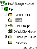
Click on the Add Host... button in the Host Folder Properties pane as shown in Figure 7-18.
Figure 7-18: Host Folder Properties Pane

Type the following information in the Add a Host pane as shown in Figure 7-19:
Host name
Host IP address
Figure 7-19: Adding Host Information
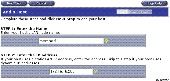
Click Next Step.
Type the port worldwide name of one of the Fibre Channel adapters on page 2 of the Add a Host pane as shown in Figure 7-20.
Note
Use the port worldwide name (WWN) obtained by issuing the
wwidmgr -show portcommand. Do not use the host WWN obtained by issuing thewwidmgr -show adapteror consoleshow devcommands unless they are the same as the port WWN.
Select Tru64 UNIX as the operating system, then click on the Next Step button.
Figure 7-20: Add a Host Page Two
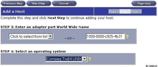
Add any comments pertaining to this host, then click on Finish to add the host as shown in Figure 7-21.
Figure 7-21: Adding a Host Page Three
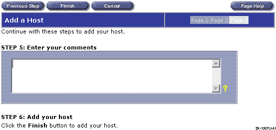
When the operation is complete, click on OK as shown in
Figure 7-22.
Figure 7-22: Operation Was Successful

Verify that the information in the Host Properties pane is correct as shown in Figure 7-23.
Figure 7-23: Host Properties Pane
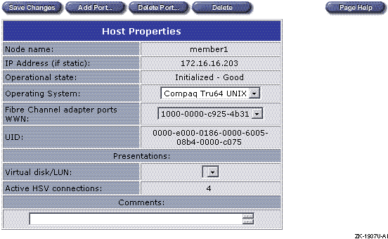
Click on the Add Port... button to add another Fibre Channel adapter.
Enter the port WWN of the second Fibre Channel adapter in the Add a Host Port pane as shown in Figure 7-24 and click on Finish.
Figure 7-24: Adding Another Fibre Channel Adapter to the Host
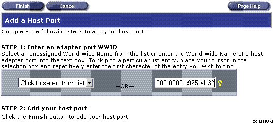
Click on OK.
Verify that the information in the Host Properties window is correct. (See Figure 7-23.) The WWN of both Fibre Channel adapters can be selected.
Note
If you have additional Fibre Channel adapters on the host, repeat steps 11 through 14 to add them.
Click on Save Changes, then click on OK.
Repeat steps 3 through 15 to add additional hosts.
After adding the cluster member systems (hosts)
to the Enterprise Virtual Array configuration, the next step is
to create a folder for the virtual disks, then create the virtual
disks.
7.9.2.5 Creating a Virtual Disk Folder and Virtual Disks
To create a folder and virtual disks for the Tru64 UNIX and TruCluster Server software installation follow these steps:
Select Virtual Disks in the navigation pane as shown in
Figure 7-25.
Figure 7-25: Selecting the Virtual Disks
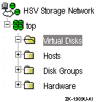
Click on the Create Folder... button in the Virtual Disk Folder Properties pane as shown in Figure 7-26.
Figure 7-26: Preparing to Create a Folder or Virtual Disk

In the Create a Folder window (Figure 7-27), provide a name for the folder, and any comment you may have. Click on Finish to create the folder.
Note
Step 3 of Figure 7-27 directs you to "Click the Create Folder button to create your folder." There is no Create Folder button. Click on the Finish button to create the folder.
Figure 7-27: Creating a Folder for Virtual Disks
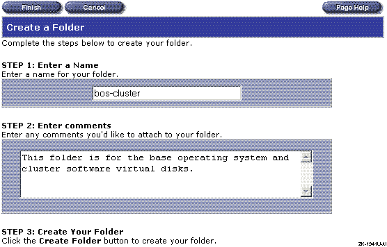
Click on OK in the Operation Was Successful pane as shown in Figure 7-22 to continue.
Select the folder that is to hold the virtual disks in the
navigation pane as shown in
Figure 7-28.
Figure 7-28: Select the Folder to Hold Virtual Disks
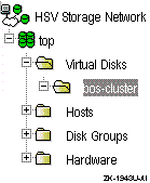
Click on the Create VD Fam... button in the Virtual Disk Folder Properties pane as shown in Figure 7-29.
Figure 7-29: Virtual Disk Folder Properties
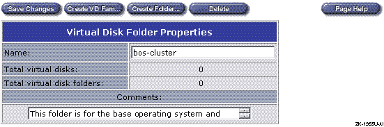
Provide the required information for each of the following items in the Create a Virtual Disk Family window as shown in Figure 7-30:
Virtual disk name.
Disk group.
Level of data protection (redundancy level: Vraid0 — none; Vraid5 — parity; Vraid1 — mirroring).
Size of the virtual disk in GB.
Write cache policy.
Read cache policy. Read caching is turned on by default. Select off to turn off read caching.
Read/Write or Read Only. The default is for the virtual disk to be Read/Write. Select Read Only if the virtual disk is to be a read-only disk.
OS unit ID. The OS unit ID will allow you to select the virtual disk when you install the software. The OS unit ID must be unique across the entire LAN, not just the HSV110 controllers. Numbers between 1 and 32767 (inclusive) can be used.
Host to which the virtual disk will be presented. You can only select one host. Others will be added later.
Preferred path for the virtual disk when both controllers are started. Select a controller and whether or not you want the virtual disk to fail back to that controller if it is restarted and rejoins the other controller.
Click on Finish to go to the second page of the virtual disk creation sequence.
Figure 7-30: Creating a Virtual Disk
On page 2 of the Create a Virtual Disk Family window (Figure 7-31), type a LUN number.
Figure 7-31: Page 2 of the Create a Virtual Disk Family Pane
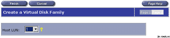
Click on Finish to create the virtual disk.
Click on OK as shown in Figure 7-32.
Figure 7-32: Successful Virtual Disk Creation
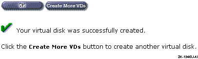
In the Navigation pane, select Active for the virtual disk
just created as shown in
Figure 7-33.
Figure 7-33: Selecting the Active Virtual Disk
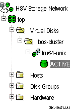
Click on the Present... button in the Virtual Disk Active Properties pane as shown in Figure 7-34.
Figure 7-34: Preparing to Present the Virtual Disk to Another Host
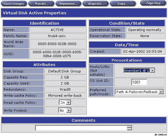
To present this virtual disk to another host, select that host in the Present Virtual Disk pane, as shown in Figure 7-35, then click on Finish.
Figure 7-35: Selecting Another Host for Virtual Disk Presentation
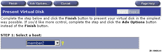
Click on OK.
Verify the entries in the Virtual Disk Active Properties
pane as shown in
Figure 7-36.
The Presentations section provides member system at LUN entries,
for example,
member1 @ 1
and
member2 &
1.
Figure 7-36: Verify the Virtual Disk Properties
Repeat steps 12 through 15 to present this virtual disk to other hosts.
Click on Save Changes, then click on OK.
Repeat steps 5 through 17 to add the remaining virtual disks.
7.10 Preparing to Install, and installing the Software
This section covers the remaining steps you must complete to install the Tru64 UNIX and TruCluster Server software:
Set the device unit number of the disk where you will install the base operating system software, and set the device unit number of the first cluster member boot disk. Setting the device unit number allows the installation scripts to recognize the disks. (See Section 7.10.1.)
Verify that the console recognizes these disks as valid boot devices. (See Section 7.10.2.)
Install the base operating system. (See Section 7.10.3.)
If you are not installing TruCluster Server software, reset
the
bootdef_dev
console environment variable to ensure that there is a path to
the boot disk if the RAID array controllers have failed over.
(See
Section 7.10.4.)
Determine the
dskn
to use for
cluster installation.
(See
Section 7.10.5.)
Label the disks to be used for cluster installation. (See Section 7.10.6.)
Install the TruCluster Server software. (See Section 7.10.7.)
Add additional cluster members. (See Section 7.10.8.)
7.10.1 Set the Device Unit Number
The device unit number is a subset of the device name as shown in
a
show device
console display.
For example,
in the device name
dga1001.1001.0.7.0, the
device unit number is
1001
(as in
dga1001).
The console uses this device unit
number to identify a storage unit.
When you set a device unit
number, you are really setting an alias for the device worldwide
name (WWN).
The 64-bit WWN is too large to be used as the device
unit number, so an alias is used instead.
This section describes how to use the
wwidmgr
-quickset
command to set the device unit number for the
Fibre Channel disks to be used as the Tru64 UNIX Version 5.1B installation disk or
cluster member system boot disks.
To set the device unit number for a Fibre Channel device, follow these steps:
From
Table 7-3
or
Table 7-4, obtain the UDID (OS unit ID)
for the virtual disk to be used as the Tru64 UNIX Version 5.1B installation disk
or cluster member system boot disks.
The OS unit ID (Enterprise
Virtual Array) is referred to as the user-defined identifier
(UDID) for the HSG80, the console software, and WWID manager
(wwidmgr).
For example, in Table 7-3 and Table 7-4, the Tru64 UNIX disk has an UDID of 1001. The UDID for the cluster member 1 boot disk is 1004, and the cluster member 2 boot disk is 1010.
From the AlphaServer console, use the
wwidmgr -clear
all
command to clear the stored Fibre Channel
wwid1,
wwid2,
wwid3,
wwid4,
N1,
N2,
N3,
and
N4
console environment variables.
You want to
start with all
wwidn
and
Nn
variables clear.
A console initialization is generally required before you can use
the
wwidmgr
command.
For example:
P00>>> init
.
.
.
P00>>> wwidmgr -clear all
P00>>> show wwid* wwid0 wwid1 wwid2 wwid3 P00>>> show n* N1 N2 N3 N4
Note
The console only creates devices for which the
wwidn console environment variable has been set, and that are accessible through an HSG80 or HSV110 N_Port as specified by theNn console environment variable also being set. These console environment variables are set with thewwidmgr -quicksetorwwidmgr -set wwidcommands. The use of thewwidmgr -quicksetcommand is shown in the next step.
Use the
wwidmgr
command with the
-quickset
option to set a device unit
number for the Tru64 UNIX Version 5.1B installation disk and the first cluster
member system boot disk.
The
wwidmgr
command with the
-quickset
option is used to define a device
unit number, based on the UDID, as an alias for the WWN for the Tru64 UNIX
installation disk and the first cluster member system boot disk.
The
wwidmgr
-quickset
utility sets the device
unit number and also provides a display of the device names and
how the disk is reachable (reachability display).
The
wwidmgr -quickset
command may generate
multiple device names for a given device unit number, because each
possible path to a storage unit is given its own device name.
Set the device unit number for the Tru64 UNIX Version 5.1B installation disk and the first cluster member system boot disk as follows:
Set the device unit number for the Tru64 UNIX Version 5.1B installation
disk to 1001 (the same as the UDID) as shown in
Example 7-7.
Example 7-7: Setting the Device Unit Number for the BOS Installation Disk
P00>>> wwidmgr -quickset -udid 1001

Disk assignment and reachability after next initialization:

6005-08b4-0001-00b2-0000-c000-025f-0000
                          via adapter:         via fc nport:        connected:
dga1001.1001.0.7.0       pga0.0.0.7.0         5000-1fe3-0008-de8c      No
dga1001.1002.0.7.0       pga0.0.0.7.0         5000-1fe3-0008-de89      Yes

dgb1001.1001.0.8.1       pgb0.0.0.8.1         5000-1fe3-0008-de8d      No
dgb1001.1002.0.8.1       pgb0.0.0.8.1         5000-1fe3-0008-de88      Yes
The
wwidmgr -quickset
command provides a
reachability display equivalent to issuing the
wwidmgr
-show reachability
command.
The reachability part of the display
provides the following information:
The WWN for the storage unit that is to be accessed
The new device name for the storage unit
The KGPSA adapters through which a connection to the storage unit is potentially available
The port WWN of the controller port(s) (N_Ports) that will be used to access the storage unit
In the
connected
column, whether the
storage unit is currently available through the KGPSA to
controller port connection
Set the device unit number for the first cluster member
system boot disk to 1005 as shown in
Example 7-8.
Example 7-8: Setting the Device Unit Number for the First Cluster Member Boot Disk
P00>>> wwidmgr -quickset -udid 1005

Disk assignment and reachability after next initialization:

6005-08b4-0001-00b2-0000-c000-025f-0000
                          via adapter:         via fc nport:        connected:
dga1001.1001.0.7.0       pga0.0.0.7.0         5000-1fe3-0008-de8c      No
dga1001.1002.0.7.0       pga0.0.0.7.0         5000-1fe3-0008-de89      Yes

dgb1001.1001.0.8.1       pgb0.0.0.8.1         5000-1fe3-0008-de8d      No
dgb1001.1002.0.8.1       pgb0.0.0.8.1         5000-1fe3-0008-de88      Yes

6005-08b4-0001-00b2-0000-c000-0277-0000
                          via adapter:         via fc nport:        connected:
dga1005.1001.0.7.0       pga0.0.0.7.0         5000-1fe3-0008-de8c      No
dga1005.1002.0.7.0       pga0.0.0.7.0         5000-1fe3-0008-de89      Yes

dgb1005.1001.0.8.1       pgb0.0.0.8.1         5000-1fe3-0008-de8d      No
dgb1005.1002.0.8.1       pgb0.0.0.8.1         5000-1fe3-0008-de88      Yes
A console initialization is required to exit the
wwidmgr, and to make the device names
available to the console
show dev
command:
P00>>> init

.
.
.
The device names have now been set for the Tru64 UNIX disk and first cluster member system boot disks.
In the reachability portion of the display, each
storageset is reachable from
KGPSA
pga
through two controller ports and from
KGPSA
pgb
through two controller ports.
Also,
the device unit number has been set for each KGPSA to
controller port connection, even if the storage unit is not currently
reachable via that connection.
7.10.2 Displaying Valid Boot Devices
The only Fibre Channel devices that are displayed by the console
show dev
command are those devices that have been
assigned to a
wwidn
environment
variable with the
wwidmgr -quickset
command.
Any device shown in the reachability display can be used
as a boot device.
The
bootdef_dev
console environment
variable can be set to any, or several, of these devices.
Also,
the cluster installation script sets the
bootdef_dev
console environment
variable to up to four of these devices.
If you issue the
show wwid*
console command
now, it will show that the environment variable
wwidn
is set for
two disks.
Also, the
show n*
command shows
that the units are accessible through four controller N_Ports as
follows:
P00>>> show wwid*
wwid0        1001 1 WWID:01000010:6005-08b4-0001-00b2-0000-c000-025f-0000
wwid1        1005 1 WWID:01000010:6005-08b4-0001-00b2-0000-c000-0277-0000
wwid2
wwid3
P00>>>show n*
N1                  	50001fe30008de8c
N2                  	50001fe30008de89
N3                  	50001fe30008de8d
N4                  	50001fe30008de88
Example 7-9
provides sample device
names as displayed by the
show dev
command after
using the
wwidmgr -quickset
command to set the
device unit numbers.
These devices are available to use as boot
devices.
Example 7-9: Sample Fibre Channel Device Names
 P00>>> show dev
dga1001.1001.0.7.0         $1$DGA1001   COMPAQ HSV110 (C)COMPAQ  1010
dga1001.1002.0.7.0         $1$DGA1001   COMPAQ HSV110 (C)COMPAQ  1010
dgb1001.1001.0.8.1         $1$DGB1001   COMPAQ HSV110 (C)COMPAQ  1010
dgb1001.1002.0.8.1         $1$DGB1001   COMPAQ HSV110 (C)COMPAQ  1010
dga1005.1001.0.7.0         $1$DGA1005   COMPAQ HSV110 (C)COMPAQ  1010
dga1005.1002.0.7.0         $1$DGA1005   COMPAQ HSV110 (C)COMPAQ  1010
dgb1005.1001.0.8.1         $1$DGB1005   COMPAQ HSV110 (C)COMPAQ  1010
dgb1005.1002.0.8.1         $1$DGB1005   COMPAQ HSV110 (C)COMPAQ  1010
dka500.5.0.2000.1          DKA500                        RRD47  1206
dkb0.0.0.2001.1            DKB0                       RZ1CD-CS  0306

.
.
.
pga0.0.0.7.0               PGA0        WWN 2000-0000-c928-2c95
pgb0.0.0.8.1               PGB0        WWN 2000-0000-c925-2c50

.
.
.
Note
The only Fibre Channel devices displayed by the console
show devcommand are those devices that have been assigned to awwidn environment variable.
At this point you are ready to install the Tru64 UNIX operating
system and TruCluster Server software.
7.10.3 Install the Base Operating System
After you read the TruCluster Server Cluster Installation manual, and using the Tru64 UNIX Installation Guide as a reference, boot from the CD-ROM and perform a full installation of the Tru64 UNIX Version 5.1B operating system.
When the installation procedure displays the list of disks that are available for operating system installation as shown here, look for the identifier in the Location column. Verify the identifier from Table 7-3 or Table 7-4.
Select a disk for the root file system.  The
root file system will be placed on the "a" partition of the disk
you choose.

To visually locate a disk, enter "ping <disk>",
where <disk> is the device name (for example, dsk0) of the disk you
want to locate.  If that disk has a visible indicator light, it will
blink until you are ready to continue.

      Device      Size  Controller  Disk
      Name       in GB  Type        Model           Location
 1)    dsk0         4.0  SCSI        RZ1CD-CS        bus-1-targ-0-lun-0
 2)    dsk1         4.0  SCSI        RZ1CD-CS        bus-1-targ-1-lun-0
 3)    dsk2         4.0  SCSI        RZ1CD-CS        bus-1-targ-2-lun-0
 4)    dsk3         8.5  SCSI        HSZ80           bus-2-targ-1-lun-1
 5)    dsk4         8.5  SCSI        HSZ80           bus-2-targ-1-lun-2
 6)    dsk5         8.5  SCSI        HSZ80           bus-2-targ-1-lun-3
 7)    dsk6         8.5  SCSI        HSZ80           bus-2-targ-1-lun-4
 8)    dsk7         8.5  SCSI        HSZ80           bus-2-targ-1-lun-5
 9)    dsk8         8.5  SCSI        HSZ80           bus-2-targ-1-lun-6
10)    dsk9         2.0  SCSI        HSV110          IDENTIFIER=1001
11)    dsk13        3.0  SCSI        HSV110          IDENTIFIER=1005
Record the
/dev/disk/dskn
value (dsk9)
for the Tru64 UNIX disk that
matches the identifier (1001).
(See
Table 7-3
or
Table 7-4.)
Complete the installation, following the instructions in the Tru64 UNIX Installation Guide.
If you are only installing the base operating system, and not
installing TruCluster Server, set the
bootdef_dev
console environment
variable to multiple paths before you boot the operating system.
(See
Section 7.10.4.)
7.10.4 Reset the bootdef_dev Console Environment Variable
After installing the cluster software, shut down the operating
system.
Use the console
show device
command
to verify that the
bootdef_dev
console environment
variable is set to select multiple paths to the boot
device and not just one path.
If it is set to select only one path to the boot device, set it to select multiple paths as follows:
Examine the reachability display provided by the
wwidmgr -show reachability
command for the
device names that can access the storage unit from which you are
booting.
Set the
bootdef_dev
console environment variable to provide multiple paths to the
boot disk.
Notes
Choose device names that show up as both
YesandNoin the reachability displayconnectedcolumn. Note, that for multiple-bus failover, only one controller is normally active for a storage unit. You must ensure that the unit is reachable if the controllers have failed over.Use device names for at least two host bus adapters.
For example, to ensure that you have a connected boot path in case of a failed host bus adapter or controller failover, choose device names for multiple host bus adapters and each controller port. If you use the reachability display for member system 1's boot disk as shown in Example 7-8, choose all of the following device names when setting the
bootdef_devconsole environment variable for the first cluster member system:dga1001.1001.0.7.0 dga1001.1002.0.7.0 dgb1001.1001.0.8.1 dgb1001.1002.0.8.1
If the
bootdef_devconsole environment variable ends up with all boot paths in an unconnected state, you can use theffautoorffnextconsole environment variables to force a boot device from anot connectedto aconnectedstate.The
ffautoconsole environment variable is effective only during autoboots (boots other than manual boots). Use theset ffauto onconsole command to enableffauto. (The default forffautoisoff.) It is stored in nonvolatile memory so it persists across system resets and power cycles.During an autoboot, the console attempts to boot from each connected device listed in the
bootdef_devconsole environment variable. Ifffautoison, and if the end of devices listed inbootdef_devis reached without successfully booting, the console starts again at the beginning of the devices listed in thebootdef_defconsole environment variable. This time, devices that are not connected are changed toconnectedand an attempt is made to boot from that device.The
ffnextconsole environment variable is a one-time variable. It does not persist across a system reset, power cycle, or reboot. This variable may be used (set ffnext on) to cause the next command to anot connecteddevice to change the state toconnected. After the command has been executed, theffnextvariable is automatically set tooff, so it has no further effect.For more information on using the
ffautoandffnextconsole environment variables, see the Wwidmgr User's Manual.
Set the
bootdef_dev
console environment
variable for the base operating system boot disk to a comma-separated list
of several of the boot paths that show up in the
reachability display (wwidmgr -show reachability).
You must
initialize the system to use any of the device names in the
bootdef_dev
variable as follows:
P00>>> set bootdef_dev \
dga1001.1001.0.7.0,dga1001.1002.0.7.0 \
dgb1001.1001.0.8.1,dgb1001.1002.0.8.1
POO>>> init
Note
The console System Reference Manual (SRM) software guarantees that you can set the
bootdef_devconsole environment variable to a minimum of four device names. You may be able to set it to five, but only four are guaranteed.
7.10.5 Determining /dev/disk/dskn to Use for a Cluster Installation
Before installing the TruCluster Server software, you must
determine which
/dev/disk/dskn
to use
for the various TruCluster Server disks.
To determine the
/dev/disk/dskn
to use
for the cluster disks, follow these steps:
With the Tru64 UNIX Version 5.1B operating system at single-user or multi-user
mode, use the hardware manager utility (hwmgr) with
the
-view devices
option to display all devices on
the system.
Pipe the command through the
grep
utility to search for any items with the
IDENTIFIER
qualifier:
# hwmgr -view dev | grep IDENTIFIER
 HWID: Device Name          Mfg      Model            Location
 --------------------------------------------------------------------
   86: /dev/disk/dsk9c      COMPAQ   HSV110 (C)COMPAQ IDENTIFIER=1001
   87: /dev/disk/dsk10c     COMPAQ   HSV110 (C)COMPAQ IDENTIFIER=1002
   88: /dev/disk/dsk11c     COMPAQ   HSV110 (C)COMPAQ IDENTIFIER=1003
   89: /dev/disk/dsk12c     COMPAQ   HSV110 (C)COMPAQ IDENTIFIER=1004
   90: /dev/disk/dsk13c     COMPAQ   HSV110 (C)COMPAQ IDENTIFIER=1005
   91: /dev/disk/dsk14c     COMPAQ   HSV110 (C)COMPAQ IDENTIFIER=1006
   92: /dev/disk/dsk15c     COMPAQ   HSV110 (C)COMPAQ IDENTIFIER=1007
   93: /dev/disk/dsk16c     COMPAQ   HSV110 (C)COMPAQ IDENTIFIER=1008
   94: /dev/disk/dsk17c     COMPAQ   HSV110 (C)COMPAQ IDENTIFIER=1009
   95: /dev/disk/dsk18c     COMPAQ   HSV110 (C)COMPAQ IDENTIFIER=1010
   96: /dev/disk/dsk19c     COMPAQ   HSV110 (C)COMPAQ IDENTIFIER=1011
   97: /dev/disk/dsk20c     COMPAQ   HSV110 (C)COMPAQ IDENTIFIER=1012
   98: /dev/disk/dsk21c     COMPAQ   HSV110 (C)COMPAQ IDENTIFIER=1013
If you know that you have set the UDID for a large number of disks, you can also search for the UDID:
# hwmgr -view dev | grep IDENTIFIER | grep 1002
 HWID: Device Name          Mfg      Model            Location
 --------------------------------------------------------------------
   87: /dev/disk/dsk10c     COMPAQ   HSV110 (C)COMPAQ IDENTIFIER=1002
Search the display for the identifiers for each of the
cluster installation disks and record the
/dev/disk/dskn
values in
Table A-1.
If you use the
grep
utility to search for
a specific UDID, for example,
hwmgr -view dev | grep IDENTIFIER=1002, repeat
the command to determine the
/dev/disk/dskn
for each of the remaining cluster disks.
Record the information for use
when you install the cluster software.
You must label the disks before you install cluster software.
7.10.6 Label the Disks to Be Used to Create the Cluster
Before you run
clu_create
to create the
first cluster member or
clu_add_member
to add
subsequent cluster members, you must label the disks to be used
for cluster software.
On the system where you installed the Tru64 UNIX operating system,
if you have not already done so, boot the system.
Determine the
/dev/disk/dskn
values
to use for cluster installation.
(See
Table 7-3
or
Table 7-4.)
Initialize disklabels for all disks needed to create the
cluster.
The example uses disks
dsk10
(/var),
dsk11
(Quorum),
dsk16
[cluster root (/)],
and
dsk17
(/usr).
For example:
# disklabel -z dsk16
  disklabel: Disk /dev/rdisk/dsk16c is unlabeled
#disklabel -rw dsk16 HSV110
7.10.7 Install the TruCluster Server Software and Create the First Cluster Member
After labeling the disks, use the TruCluster Server Cluster Installation procedures and install the TruCluster Server software on the first cluster member (the system where you just installed Tru64 UNIX).
After installing the TruCluster Server software subsets, run the
clu_create
command to create the first cluster
member using the procedures in the TruCluster Server
Cluster Installation
manual.
7.10.8 Add Additional Systems to the Cluster
To add additional systems to the cluster, follow this procedure:
On the system where you installed the Tru64 UNIX operating system and TruCluster Server software, boot the system into the cluster as a single-member cluster.
Referring to the TruCluster Server
Cluster Installation
manual
procedures, use
clu_add_member
to add a cluster
member.
Before you boot the system being added to the cluster, on the newly added cluster member:
Use the
wwidmgr
utility with the
-quickset
option to set the device unit number
for the member system boot disk as shown in
Example 7-10.
For member system 2 in the example
configuration, it is the storage unit with OS unit ID 1010 (Table 7-4):
Example 7-10: Setting Device Unit Number for Additional Member System
P00>>> wwidmgr -quickset -udid 1010

Disk assignment and reachability after next initialization:

6005-08b4-0001-00b2-0000-c000-029d-0000
                          via adapter:         via fc nport:        connected:
dga1010.1001.0.7.0       pga0.0.0.7.0         5000-1fe3-0008-de8c      No
dga1010.1002.0.7.0       pga0.0.0.7.0         5000-1fe3-0008-de89      Yes

dgb1010.1001.0.8.1       pgb0.0.0.8.1         5000-1fe3-0008-de8d      No
dgb1010.1002.0.8.1       pgb0.0.0.8.1         5000-1fe3-0008-de88      Yes

P00>>> init
Set the
bootdef_dev
console environment variable to
one reachable path (Yes
in the connected
column of
Example 7-10) to
the member system boot disk:
P00>>> set bootdef_dev dga1010.1002.0.7.0
Boot
genvmunix
on the newly added
cluster member system.
Each installed subset will be configured
and a new kernel will be built and installed.
Boot the new cluster member system into the cluster and complete the cluster installation.
Repeat steps 2 and 3 for other cluster member systems.
7.11 Converting the HSG80 from Transparent to Multiple-Bus Failover Mode
If you are migrating from Tru64 UNIX Version 4.0F or Version 4.0G and TruCluster Software Products Version 1.6 to Tru64 UNIX Version 5.1B and TruCluster Server Version 5.1B, you may want to change from transparent failover to multiple-bus failover to take advantage of multibus support in Tru64 UNIX Version 5.1B and multiple-bus failover mode and the ability to create a no-single-point-of-failure (NSPOF) cluster.
If you are using transparent failover mode with
Tru64 UNIX Version 5.1B and TruCluster Server Version 5.1B, you may want to
take advantage of the ability to create an
NSPOF configuration, and the availability that multiple-bus failover
provides over transparent failover mode.
7.11.1 Overview
The change in failover modes cannot be accomplished with a simple
SET MULTIBUS COPY=THIS
HSG80 CLI command because:
Unit offsets are not changed by the HSG80
SET
MULTIBUS_FAILOVER COPY=THIS
command.
Each path between a Fibre Channel host bus adapter in a host computer and an active host port on an HSG80 controller is a connection. During Fibre Channel initialization, when a controller becomes aware of a connection to a host bus adapter through a switch or hub, it adds the connection to its table of known connections. The unit offset for the connection depends on the failover mode in effect at the time that the connection is discovered. In transparent failover mode, host connections to port 1 default to an offset of 0; host connections on port 2 default to an offset of 100. Host connections on port 1 can see units 0 through 99; host connections on port 2 can see units 100 through 199.
In multiple-bus failover mode, host connections on either port 1 or 2 can see units 0 through 199. In multiple-bus failover mode, the default offset for both ports is 0.
If you change the failover mode from transparent failover to multiple-bus failover, the offsets in the table of known connections remain the same as if they were for transparent failover mode; the offset on port 2 remains 100. With an offset of 100 on port 2, a host cannot see units 0 through 99 on port 2. This reduces the availability. Also, if you have only a single HSG80 controller and lose the connection to port 1, you lose access to units 0 through 99.
Therefore, if you want to change from transparent failover to multiple-bus failover mode, you must change the offset in the table of known connections for each connection that has a nonzero offset.
Note
Disconnecting and then reconnecting the cables does no good because a connection that is added to the table remains in the table until you delete the connection.
The system can access a storage device through only one HSG80 port. The system's view of the storage device is not changed when the HSG80 is placed in multiple-bus failover mode.
In transparent failover mode, the system accesses storage units D0 through D99 through port 1 and units D100 through D199 through port 2. In multiple-bus failover mode, you want the system to be able to access all units through all four ports.
7.11.2 Procedure to Convert from Transparent to Multiple-bus Failover Mode
To change from transparent failover to multiple-bus failover mode by resetting the unit offsets and modifying the systems' view of the storage units, follow these steps:
Shut down the operating systems on all host systems that are accessing the HSG80 controllers that you want to change from transparent failover to multiple-bus failover mode.
At the HSG80, set multiple-bus failover as follows. Before putting the controllers in multiple-bus failover mode, you must remove any previous failover mode:
HSG80> SET NOFAILOVER
HSG80> SET MULTIBUS_FAILOVER COPY=THIS
Note
Use the controller that you know has the good configuration information.
If this HSG80 is being used in an arbitrated loop topology (port
topology is set to
LOOP_HARD),
you need to set a unique AL_PA address for each port
because all of the ports can be active at the same time.
(The convention in transparent failover mode is to use the same AL_PA
address for Port 1 on both controllers and the same
AL_PA address for Port 2 on both controllers.)
The following example sets the ports on two HSG80 controllers
off line, sets the
PORT_x_AL_PA
value for multiple-bus failover mode, and sets the ports on line.
HSG80> set this port_1_topology = offline
HSG80> set this port_2_topology = offline
HSG80> set other port_1_topology = offline
HSG80> set other port_2_topology = offline
HSG80> set this PORT_1_AL_PA  = 01
HSG80> set this PORT_2_AL_PA  = 02
HSG80> set other PORT_1_AL_PA  = 04
HSG80> set other PORT_2_AL_PA  = 08
Execute the
SHOW CONNECTION
command to
determine which connections have a nonzero offset as follows:
HSG80> SHOW CONNECTION
Connection                                                                Unit
   Name      Operating system    Controller  Port    Address    Status   Offset

!NEWCON49      TRU64_UNIX           THIS       2      230813   OL this     100
           HOST_ID=1000-0000-C920-DA01         ADAPTER_ID=1000-0000-C920-DA01

!NEWCON50      TRU64_UNIX           THIS       1      230813   OL this       0
           HOST_ID=1000-0000-C920-DA01         ADAPTER_ID=1000-0000-C920-DA01

!NEWCON51      TRU64_UNIX           THIS       2      230913   OL this     100
           HOST_ID=1000-0000-C920-EDEB         ADAPTER_ID=1000-0000-C920-EDEB

!NEWCON52      TRU64_UNIX           THIS       1      230913   OL this       0
           HOST_ID=1000-0000-C920-EDEB         ADAPTER_ID=1000-0000-C920-EDEB

!NEWCON53      TRU64_UNIX           OTHER      1      230913   OL other      0
           HOST_ID=1000-0000-C920-EDEB         ADAPTER_ID=1000-0000-C920-EDEB

!NEWCON54      TRU64_UNIX           OTHER      1      230813   OL other      0
           HOST_ID=1000-0000-C920-DA01         ADAPTER_ID=1000-0000-C920-DA01

!NEWCON55      TRU64_UNIX           OTHER      2      230913   OL other    100
           HOST_ID=1000-0000-C920-EDEB         ADAPTER_ID=1000-0000-C920-EDEB

!NEWCON56      TRU64_UNIX           OTHER      2      230813   OL other    100
           HOST_ID=1000-0000-C920-DA01         ADAPTER_ID=1000-0000-C920-DA01

!NEWCON57      TRU64_UNIX           THIS       2               offline     100
           HOST_ID=1000-0000-C921-09F7         ADAPTER_ID=1000-0000-C921-09F7

!NEWCON58      TRU64_UNIX           OTHER      1               offline       0
           HOST_ID=1000-0000-C921-09F7         ADAPTER_ID=1000-0000-C921-09F7

!NEWCON59      TRU64_UNIX           THIS       1               offline       0
           HOST_ID=1000-0000-C921-09F7         ADAPTER_ID=1000-0000-C921-09F7

!NEWCON60      TRU64_UNIX           OTHER      2               offline     100
           HOST_ID=1000-0000-C921-09F7         ADAPTER_ID=1000-0000-C921-09F7

!NEWCON61      TRU64_UNIX           THIS       2      210513   OL this     100
           HOST_ID=1000-0000-C921-086C         ADAPTER_ID=1000-0000-C921-086C

!NEWCON62      TRU64_UNIX           OTHER      1      210513   OL other      0
           HOST_ID=1000-0000-C921-086C         ADAPTER_ID=1000-0000-C921-086C

!NEWCON63      TRU64_UNIX           OTHER      1               offline       0
           HOST_ID=1000-0000-C921-0943         ADAPTER_ID=1000-0000-C921-0943

!NEWCON64      TRU64_UNIX           OTHER      1      210413   OL other      0
           HOST_ID=1000-0000-C920-EDA0         ADAPTER_ID=1000-0000-C920-EDA0

!NEWCON65      TRU64_UNIX           OTHER      2      210513   OL other    100
           HOST_ID=1000-0000-C921-086C         ADAPTER_ID=1000-0000-C921-086C

.
.
.
The following connections are shown to have nonzero offsets:
!NEWCON49,
!NEWCON51,
!NEWCON55,
!NEWCON56,
!NEWCON57,
!NEWCON60,
!NEWCON61, and
!NEWCON65
Set the unit offset to 0 for each connection that has a nonzero unit offset:
HSG80> SET !NEWCON49 UNIT_OFFSET = 0
HSG80> SET !NEWCON51 UNIT_OFFSET = 0
HSG80> SET !NEWCON55 UNIT_OFFSET = 0
HSG80> SET !NEWCON56 UNIT_OFFSET = 0
HSG80> SET !NEWCON57 UNIT_OFFSET = 0
HSG80> SET !NEWCON60 UNIT_OFFSET = 0
HSG80> SET !NEWCON61 UNIT_OFFSET = 0
HSG80> SET !NEWCON65 UNIT_OFFSET = 0
At the console of each system accessing storage units on this HSG80, follow these steps:
Use the
wwid
manager
(wwidmgr) to show the Fibre Channel
environment variables and determine which units are reachable by
the system.
This is the information the console uses, when not
in
wwidmgr
mode, to find Fibre Channel
devices:
P00>>> wwidmgr -show ev
wwid0    133 1 WWID:01000010:6000-1fe1-0000-0d60-0009-8080-0434-002e
wwid1    131 1 WWID:01000010:6000-1fe1-0000-0d60-0009-8080-0434-002f
wwid2    132 1 WWID:01000010:6000-1fe1-0000-0d60-0009-8080-0434-0030
wwid3
N1       50001fe100000d64
N2
N3
N4
Note
You must set the console to diagnostic mode to use the
wwidmgrcommand for the following AlphaServer systems: AS1200, AS4x00, AS8x00, GS60, GS60E, and GS140. Set the console to diagnostic mode as follows:P00>>> set mode diag Console is in diagnostic mode P00>>>
For each
wwidn
line,
record the unit number (131, 132, and 133) and worldwide name for the
storage unit.
The unit number is the first field in the display
(after
wwidn).
The
Nn
value is the
HSG80 port being used to access the storage units.
Clear the
wwidn
and
Nn
environment
variables:
P00>>> wwidmgr -clear all
Initialize the console:
P00>>> init
Use the
wwid
manager with the
-quickset
option to set up the device and port path information for the storage
units from where each system will need to boot.
Each system may need
to boot from the base operating system disk.
Each system will need to
boot from its member system boot disk.
Using the storage units from
the example, cluster member 1 will need access to the storage units
with UDIDs 131 (member 1 boot disk) and 133 (Tru64 UNIX disk).
Cluster member 2 will need access to the storage units with UDIDs 132
(member 2 boot disk) and 133 (Tru64 UNIX disk).
Set up the device
and port path for cluster member 1 as follows:
P00>>> wwidmgr -quickset -udid 131

.
.
.
P00>>> wwidmgr -quickset -udid 133

.
.
.
Initialize the console:
P00>>> init
Verify that the storage units and port path information is set up, and then reinitialize the console. The following example shows the information for cluster member 1:
P00>>> wwidmgr -show ev
wwid0    133 1 WWID:01000010:6000-1fe1-0000-0d60-0009-8080-0434-002e
wwid1    131 1 WWID:01000010:6000-1fe1-0000-0d60-0009-8080-0434-002f
wwid2
wwid3
N1       50001fe100000d64
N2       50001fe100000d62
N3       50001fe100000d63
N4       50001fe100000d61
P00>>> init
Set the
bootdef_dev
console environment variable to
the member system boot device.
Use the paths shown in the
reachability display of the
wwidmgr -quickset
command for the appropriate device (Section 7.10.4).
Repeat steps a through h on each system accessing devices on the HSG80.
7.12 Using the Storage System Scripting Utility
For large or complex configurations, you can use the Storage System Scripting Utility (SSSU or scripting utility) instead of the graphical user interface (GUI). The scripting utility is a character-cell interface to the HSV Element Manager.
The scripting utility executable is available in the operating
system solutions kit, and is named
sssu
or
SSSU.EXE, depending on the operating system.
You can run the scripting utility from the CD-ROM
SSSU
directory, or copy it to your system (for
example,
/usr/local/bin).
Ensure that you
change permissions so the the file is executable on your
Tru64 UNIX system.
Note
If password access to the HSV110 controllers is enabled, it has to be set up from the HSV110 Element Manager before you can use the scripting utility; you cannot set password access using the scripting utility.
7.12.1 Starting the Scripting Utility
You can start the scripting utility in two ways:
By providing arguments on the command line. In this case, the commands are echoed, executed, and then the scripting utility exits to the command line.
Enclose the command arguments in double quotation marks (" ").
The following example uses the scripting utility with command-line arguments:
# sssu "FILE /san/scripts/eva01-config.ssu"

.
.
.
Note
The file is not required to have an extension.
When started without command-line arguments, no commands are
executed and the
NoCellSelected>
prompt is displayed.
Before any useful commands can be issued, you have to select the HSV110 Element Manager (so the scripting utility can communicate with it), and add a storage cell (the set of HSV110 controllers you want to use).
When you select the cell, the prompt will change to the name of
the cell as shown in
Example 7-11.
Example 7-11: Preparing the Scripting Utility to Access an HSV110 Controller Pair
# sssu

SSSU version 3.0 Build 92
EMClientAPI Version 1.6, Build date: Sep 14 2001

NoCellSelected> SELECT MANAGER swmaxxxxxx Username=XXXXX Password=XXXXX
NoCellSelected> SELECT CELL Enterprise10
Enterprise10>
Note
If the HSV Element Manager GUI has not been used to initialize the HSV110 controller pair, you can initialize it with the
ADD CELLcommand. You must select the unitialized cell, add the cell (providing it with the cell name), then select the initialized cell. For example:# sssu SSSU version 3.0 Build 92 EMClientAPI Version 1.6, Build date: Sep 14 2001 NoCellSelected> SELECT MANAGER swmaxxxxxx Username=XXXXX Password=XXXXX NoCellSelected> SHOW CELL Cells available on this Manager: Uninitialized Storage System NoCellSelected> SELECT CELL "Uninitialized Storage System" Uninitialized Storage System> ADD CELL Enterprise10 Uninitialized Storage System> SELECT CELL Enterprise10 Enterprise10>
7.12.2 Capturing an Existing Configuration with the Scripting Utility
After you have set up an Enterprise Virtual Array configuration with the GUI,
you can use the scripting utility to save the configuration.
The
CAPTURE
CONFIGURATION
command accesses the
selected cell and creates a script, which can be used to re-create
the configuration (if necessary).
The default output for the
CAPTURE
CONFIGURATION
command is standard output.
Provide a
file name if you want the configuration script output redirected
to a file.
You can use the script created by the scripting
utility to rebuild the configuration, if necessary,
or use it as a model to create other scripts for more complex
configurations.
Example 7-12
shows how to capture
the present configuration.
Example 7-12: Capturing the Enterprise Virtual Array Configuration
# sssu

SSSU version 3.0 Build 92
EMClientAPI Version 1.6, Build date: Sep 14 2001

NoCellSelected> SELECT MANAGER swmaxxxxxx Username=XXXXX Password=XXXXX
NoCellSelected> SELECT CELL Enterprise10
Enterprise10> CAPTURE CONFIGURATION /san/scripts/create-enterprise10.ssu
    CAPTURE CONFIGURATION may take awhile.  Do not modify configuration
    until command is complete.

........................
    Capture complete and successful
7.12.3 Using the Scripting Utility with the File Command
If you are creating a large or complex configuration, or if you
have to re-create a configuration, use the scripting utility with
the
FILE
command.
The
FILE
command reads commands from the named file.
An
end-of-file or an
EXIT
command causes a return
to the command prompt.
Note
Do not attempt to re-create an HSV110 configuration with a file created by the
CAPTURE
CONFIGURATION
command if any portion of the of the original configuration still exists; the script will terminate execution.
You can re-create the configuration captured in
Example 7-12
as shown in
Example 7-13.
Example 7-13: Using the Scripting Utility File Command with a Script File
# sssu

SSSU version 3.0 Build 92
EMClientAPI Version 1.6, Build date: Sep 14 2001

NoCellSelected> file /san/scripts/create-enterprise10.ssu

.
.
.
7.12.4 Creating Script Files for Use with the Scripting Utility
The easiest way to learn how to write a script file is to create a configuration using the GUI, capture the configuration, then use the generated file as a model.
The Scripting Utility V1.0 for Enterprise Virtual Array Reference Guide provides descriptions of the scripting utility commands.
Note
Whenever you issue commands:
Specified names must use the full path (
\hosts\member1)If a pathname contains a space, the entire name must be enclosed in double quotation marks (" ") such as (
"\Virtual Disks\bos-cluster\tru64-unix\Active")
The script file created by the
CAPTURE
CONFIGURATION
command for the example configuration
described in
Section 7.9.2
and
Table 7-4
is shown in
Example 7-14.
Note
Each command must be on one line; there is no line continuation character or comment character.
Even though it is not supported, this example uses the slash character (
/) as a line continuation character to ensure that all the text is shown.A blank line may be used to separate portions of your script. A blank line has no effect on execution of the script.
Use the
ON_ERROR
option to the
SET
OPTIONS
command to determine how you want the scripting
utility to react to an error condition in your script.
When set
to
HALT_ON_ERROR, an error condition in the
script causes the script to cease execution, but the scripting
utility will not exit until you press a terminal key.
This
allows you to observe the error.
If you encounter an error in your script, copy the script to a new file. Edit the new script file and correct the error. Delete all the commands that executed correctly, except the initial commands to set the options, select the manager, and select the cell. The script will not function if you do not select the manager and cell. After editing the new script, use the scripting utility to execute the new script file.
Note
There is a default 10-second delay between issued commands. This can add up to a lot of time for a very large script. Setting the delay to a shorter delay time will save time. If the delay is too short and causes an error condition, and if you have set
HALT_ON_ERROR, you will know where the error occurred. You can copy the script as previously mentioned, deleting the correctly executed commands, and reset the time delay to a longer delay. Reexecute the script after making the modifications.
Example 7-14: Script File Used to Create the Example Configuration
SET OPTIONS ON_ERROR=HALT_ON_ERROR COMMAND_DELAY=1
SELECT MANAGER swmaxxxx Username=xxxx Password=xxxx
SELECT CELL "enterprise10"

ADD FOLDER "\Virtual Disks\bos-cluster" COMMENT="Folder for the BOS and TCR /
software virtual disks."

ADD HOST "\Hosts\member1" OPERATING_SYSTEM=TRU64 WORLD_WIDE_NAME=1000-0000-C925-3B7C /
IP=127.1.2.20
SET HOST "\Hosts\member1" ADD_WORLD_WIDE_NAME=1000-0000-C925-1EA1

ADD HOST "\Hosts\member2" OPERATING_SYSTEM=TRU64 WORLD_WIDE_NAME=1000-0000-C925-3B7D /
IP=127.1.2.21
SET HOST "\Hosts\member2" ADD_WORLD_WIDE_NAME=1000-0000-C927-1EA2

ADD STORAGE "\Virtual Disks\bos-cluster\tru64-unix" GROUP="\Disk Groups\Default /
Disk Group" SIZE=2 REDUNDANCY=VRAID5 MIRRORED_WRITEBACK READ_CACHE /
NOWRITE_PROTECT OS_UNIT_ID=1001 PREFERRED_PATH=PATH_A_BOTH
ADD LUN 1 STORAGE="\Virtual Disks\bos-cluster\tru64-unix\ACTIVE" HOST="\Hosts\member1"
ADD LUN 1 STORAGE="\Virtual Disks\bos-cluster\tru64-unix\ACTIVE" HOST="\Hosts\member2"

ADD STORAGE "\Virtual Disks\bos-cluster\clu-var" GROUP="\Disk Groups\Default /
Disk Group" SIZE=24 REDUNDANCY=VRAID5 MIRRORED_WRITEBACK READ_CACHE /
NOWRITE_PROTECT OS_UNIT_ID=1002 PREFERRED_PATH=PATH_A_BOTH
ADD LUN 2 STORAGE="\Virtual Disks\bos-cluster\clu-var\ACTIVE" HOST="\Hosts\member1"
ADD LUN 2 STORAGE="\Virtual Disks\bos-cluster\clu-var\ACTIVE" HOST="\Hosts\member2"

ADD STORAGE "\Virtual Disks\bos-cluster\clu-quorum" GROUP="\Disk Groups\Default /
Disk Group" SIZE=1 REDUNDANCY=VRAID5 MIRRORED_WRITEBACK READ_CACHE /
NOWRITE_PROTECT OS_UNIT_ID=1003 PREFERRED_PATH=PATH_A_BOTH
ADD LUN 3 STORAGE="\Virtual Disks\bos-cluster\clu-quorum\ACTIVE" HOST="\Hosts\member1"
ADD LUN 3 STORAGE="\Virtual Disks\bos-cluster\clu-quorum\ACTIVE" HOST="\Hosts\member2"

ADD STORAGE "\Virtual Disks\bos-cluster\member1-boot" GROUP="\Disk Groups\Default /
Disk Group" SIZE=3 REDUNDANCY=VRAID5 MIRRORED_WRITEBACK READ_CACHE /
NOWRITE_PROTECT OS_UNIT_ID=1004 PREFERRED_PATH=PATH_A_BOTH
ADD LUN 4 STORAGE="\Virtual Disks\bos-cluster\member1-boot\ACTIVE" HOST="\Hosts\member1"
ADD LUN 4 STORAGE="\Virtual Disks\bos-cluster\member1-boot\ACTIVE" HOST="\Hosts\member2"

ADD STORAGE "\Virtual Disks\bos-cluster\member3-boot" GROUP="\Disk Groups\Default /
Disk Group" SIZE=3 REDUNDANCY=VRAID5 MIRRORED_WRITEBACK READ_CACHE /
NOWRITE_PROTECT OS_UNIT_ID=1005 PREFERRED_PATH=PATH_A_BOTH
ADD LUN 5 STORAGE="\Virtual Disks\bos-cluster\member3-boot\ACTIVE" HOST="\Hosts\member1"
ADD LUN 5 STORAGE="\Virtual Disks\bos-cluster\member3-boot\ACTIVE" HOST="\Hosts\member2"

ADD STORAGE "\Virtual Disks\bos-cluster\member5-boot" GROUP="\Disk Groups\Default /
Disk Group" SIZE=3 REDUNDANCY=VRAID5 MIRRORED_WRITEBACK READ_CACHE /
NOWRITE_PROTECT OS_UNIT_ID=1006 PREFERRED_PATH=PATH_A_BOTH
ADD LUN 6 STORAGE="\Virtual Disks\bos-cluster\member5-boot\ACTIVE" HOST="\Hosts\member1"
ADD LUN 6 STORAGE="\Virtual Disks\bos-cluster\member5-boot\ACTIVE" HOST="\Hosts\member2"

ADD STORAGE "\Virtual Disks\bos-cluster\member7-boot" GROUP="\Disk Groups\Default /
Disk Group" SIZE=3 REDUNDANCY=VRAID5 MIRRORED_WRITEBACK READ_CACHE /
NOWRITE_PROTECT OS_UNIT_ID=1007 PREFERRED_PATH=PATH_A_BOTH
ADD LUN 7 STORAGE="\Virtual Disks\bos-cluster\member7-boot\ACTIVE" HOST="\Hosts\member1"
ADD LUN 7 STORAGE="\Virtual Disks\bos-cluster\member7-boot\ACTIVE" HOST="\Hosts\member2"

ADD STORAGE "\Virtual Disks\bos-cluster\clu-root" GROUP="\Disk Groups\Default /
Disk Group" SIZE=2 REDUNDANCY=VRAID5 MIRRORED_WRITEBACK READ_CACHE /
NOWRITE_PROTECT OS_UNIT_ID=1008 PREFERRED_PATH=PATH_B_BOTH
ADD LUN 8 STORAGE="\Virtual Disks\bos-cluster\clu-root\ACTIVE" HOST="\Hosts\member1"
ADD LUN 8 STORAGE="\Virtual Disks\bos-cluster\clu-root\ACTIVE" HOST="\Hosts\member2"

ADD STORAGE "\Virtual Disks\bos-cluster\clu-usr" GROUP="\Disk Groups\Default /
Disk Group" SIZE=8 REDUNDANCY=VRAID5 MIRRORED_WRITEBACK READ_CACHE /
NOWRITE_PROTECT OS_UNIT_ID=1009 PREFERRED_PATH=PATH_B_BOTH
ADD LUN 9 STORAGE="\Virtual Disks\bos-cluster\clu-usr\ACTIVE" HOST="\Hosts\member1"
ADD LUN 9 STORAGE="\Virtual Disks\bos-cluster\clu-usr\ACTIVE" HOST="\Hosts\member2"

ADD STORAGE "\Virtual Disks\bos-cluster\member2-boot" GROUP="\Disk Groups\Default /
Disk Group" SIZE=3 REDUNDANCY=VRAID5 MIRRORED_WRITEBACK READ_CACHE /
NOWRITE_PROTECT OS_UNIT_ID=1010 PREFERRED_PATH=PATH_B_BOTH
ADD LUN 10 STORAGE="\Virtual Disks\bos-cluster\member2-boot\ACTIVE" HOST="\Hosts\member1"
ADD LUN 10 STORAGE="\Virtual Disks\bos-cluster\member2-boot\ACTIVE" HOST="\Hosts\member2"

ADD STORAGE "\Virtual Disks\bos-cluster\member4-boot" GROUP="\Disk Groups\Default /
Disk Group" SIZE=3 REDUNDANCY=VRAID5 MIRRORED_WRITEBACK READ_CACHE /
NOWRITE_PROTECT OS_UNIT_ID=1011 PREFERRED_PATH=PATH_B_BOTH
ADD LUN 11 STORAGE="\Virtual Disks\bos-cluster\member4-boot\ACTIVE" HOST="\Hosts\member1"
ADD LUN 11 STORAGE="\Virtual Disks\bos-cluster\member4-boot\ACTIVE" HOST="\Hosts\member2"

ADD STORAGE "\Virtual Disks\bos-cluster\member6-boot" GROUP="\Disk Groups\Default /
Disk Group" SIZE=3 REDUNDANCY=VRAID5 MIRRORED_WRITEBACK READ_CACHE /
NOWRITE_PROTECT OS_UNIT_ID=1012 PREFERRED_PATH=PATH_B_BOTH
ADD LUN 12 STORAGE="\Virtual Disks\bos-cluster\member6-boot\ACTIVE" HOST="\Hosts\member1"
ADD LUN 12 STORAGE="\Virtual Disks\bos-cluster\member6-boot\ACTIVE" HOST="\Hosts\member2"

ADD STORAGE "\Virtual Disks\bos-cluster\member8-boot" GROUP="\Disk Groups\Default /
Disk Group" SIZE=3 REDUNDANCY=VRAID5 MIRRORED_WRITEBACK READ_CACHE /
NOWRITE_PROTECT OS_UNIT_ID=1013 PREFERRED_PATH=PATH_B_BOTH
ADD LUN 13 STORAGE="\Virtual Disks\bos-cluster\member8-boot\ACTIVE" HOST="\Hosts\member1"
ADD LUN 13 STORAGE="\Virtual Disks\bos-cluster\member8-boot\ACTIVE" HOST="\Hosts\member2"
7.12.5 Using the Scripting Utility to Delete Enterprise Configuration Information
If you need to delete or modify configuration information, you can use the GUI or the scripting utility. For example, if you replace a KGPSA, you need to delete the port WWN for the removed KGPSA and add the port WWN for the new KGPSA.
If you are not familiar with the correct format, use the
SHOW
commands to determine the required
format.
Example 7-15
shows the scripting utility
commands needed to remove the WWN for a KGPSA that will be
removed, and to add the WWN for the new KGPSA.
Example 7-15: Using the Scripting Utility to Reset the WWN for a Replaced KGPSA
# sssu

SSSU version 3.0 Build 92
EMClientAPI Version 1.6, Build date: Sep 14 2001

NoCellSelected> SELECT MANAGER swmaxxxxxx Username=XXXXX Password=XXXXX
NoCellSelected> SELECT CELL Enterprise10
Enterprise10> SET HOST \Hosts\member2 DELETE_WORLD_WIDE_NAME=1000-0000-c927-1ea2
Enterprise10> SET HOST \Hosts\member2 ADD_WORLD_WIDE_NAME=1000-0000-cbad-ef10
Enterprise10>
Example 7-16
shows the contents of
a script file which will delete the entire configuration set up
in
Example 7-14.
Example 7-16: Script File to Delete the Example Configuration
SET OPTIONS ON_ERROR=HALT_ON_ERROR
SELECT MANAGER swmaxxxx Username=xxxxx Password=xxxxx
SELECT CELL "top"
DELETE LUN \Hosts\member1\1
DELETE LUN \Hosts\member2\1
DELETE LUN \Hosts\member1\2
DELETE LUN \Hosts\member2\2
DELETE LUN \Hosts\member1\3
DELETE LUN \Hosts\member2\3
DELETE LUN \Hosts\member1\4
DELETE LUN \Hosts\member2\4
DELETE LUN \Hosts\member1\5
DELETE LUN \Hosts\member2\5
DELETE LUN \Hosts\member1\6
DELETE LUN \Hosts\member2\6
DELETE LUN \Hosts\member1\7
DELETE LUN \Hosts\member2\7
DELETE LUN \Hosts\member1\8
DELETE LUN \Hosts\member2\8
DELETE LUN \Hosts\member1\9
DELETE LUN \Hosts\member2\9
DELETE LUN \Hosts\member1\10
DELETE LUN \Hosts\member2\10
DELETE LUN \Hosts\member1\11
DELETE LUN \Hosts\member2\11
DELETE LUN \Hosts\member1\12
DELETE LUN \Hosts\member2\12
DELETE LUN \Hosts\member1\13
DELETE LUN \Hosts\member2\13
DELETE STORAGE "\Virtual Disks\bos-cluster\tru64-unix\ACTIVE"
DELETE STORAGE "\Virtual Disks\bos-cluster\clu-root\ACTIVE"
DELETE STORAGE "\Virtual Disks\bos-cluster\clu-usr\ACTIVE"
DELETE STORAGE "\Virtual Disks\bos-cluster\clu-var\ACTIVE"
DELETE STORAGE "\Virtual Disks\bos-cluster\clu-quorum\ACTIVE"
DELETE STORAGE "\Virtual Disks\bos-cluster\member1-boot\ACTIVE"
DELETE STORAGE "\Virtual Disks\bos-cluster\member2-boot\ACTIVE"
DELETE STORAGE "\Virtual Disks\bos-cluster\member3-boot\ACTIVE"
DELETE STORAGE "\Virtual Disks\bos-cluster\member4-boot\ACTIVE"
DELETE STORAGE "\Virtual Disks\bos-cluster\member5-boot\ACTIVE"
DELETE STORAGE "\Virtual Disks\bos-cluster\member6-boot\ACTIVE"
DELETE STORAGE "\Virtual Disks\bos-cluster\member7-boot\ACTIVE"
DELETE STORAGE "\Virtual Disks\bos-cluster\member8-boot\ACTIVE"
DELETE HOST "\Hosts\member1"
DELETE HOST "\Hosts\member2"
DELETE FOLDER "\Virtual Disks\bos-cluster\"
7.13 Using the emx Manager to Display Fibre Channel Adapter Information
The
emx
manager (emxmgr) utility
was written for the TruCluster Software Product Version 1.6 products
to be used to modify and maintain
emx
driver
worldwide name (WWN) to target ID mappings.
It is included with
Tru64 UNIX Version 5.1B and, although it is not needed to maintain WWN to
target ID mappings, you may use it with TruCluster Server Version 5.1B to:
Display the presence of KGPSA Fibre Channel adapters
Display the current Fibre Channel topology for a Fibre Channel adapter
See
emxmgr(8)emxmgr
utility.
The functionality of the
emxmgr
utility has
been added to the
hwmgr
utility
(/sbin/hwmgr show fibre, see
hwmgr_show(8)/sbin/hwmgr -help show).
The
emxmgr
utility will be removed
from the operating software at a later release.
7.13.1 Using the emxmgr Utility to Display Fibre Channel Adapter Information
The primary use of the
emxmgr
utility for TruCluster Server
is to display Fibre Channel information.
Use the
emxmgr -d
command to display the presence
of KGPSA Fibre Channel adapters on the system.
For example:
# /usr/sbin/emxmgr -d
emx0 emx1 emx2
Use the
emxmgr -t
command to display the Fibre
Channel topology for the adapter.
For example:
# emxmgr -t emx1

emx1 state information:  [1]
  Link :  connection is UP
          Point to Point
          Fabric attached
          FC DID 0x210413
  Link is SCSI bus 3 (e.g. scsi3)
          SCSI target id 7
          portname is 1000-0000-C921-07C4
          nodename is 2000-0000-C921-07C4
  N_Port at FC DID 0x210013 - SCSI tgt id 5 :  [2]
    portname 5000-1FE1-0001-8932
    nodename 5000-1FE1-0001-8930
    Present, Logged in, FCP Target, FCP Logged in,
  N_Port at FC DID 0x210113 - SCSI tgt id 1 :  [2]
    portname 5000-1FE1-0001-8931
    nodename 5000-1FE1-0001-8930
    Present, Logged in, FCP Target, FCP Logged in,
  N_Port at FC DID 0x210213 - SCSI tgt id 2 :  [2]
    portname 5000-1FE1-0001-8941
    nodename 5000-1FE1-0001-8940
    Present, Logged in, FCP Target, FCP Logged in,
  N_Port at FC DID 0x210313 - SCSI tgt id 4 :  [2]
    portname 5000-1FE1-0001-8942
    nodename 5000-1FE1-0001-8940
    Present, Logged in, FCP Target, FCP Logged in,
  N_Port at FC DID 0x210513 - SCSI tgt id 6 :  [2]
    portname 1000-0000-C921-07F4
    nodename 2000-0000-C921-07F4
    Present, Logged in, FCP Initiator, FCP Target, FCP Logged in,
  N_Port at FC DID 0xfffffc - SCSI tgt id -1 :  [3]
    portname 20FC-0060-6900-5A1B
    nodename 1000-0060-6900-5A1B
    Present, Logged in, Directory Server,
  N_Port at FC DID 0xfffffe - SCSI tgt id -1 :  [3]
    portname 2004-0060-6900-5A1B
    nodename 1000-0060-6900-5A1B
    Present, Logged in, F_PORT,
Status of the
emx1
link.
The connection is a
point-to-point fabric (switch) connection, and the link is up.
The
adapter is on SCSI bus 3 at SCSI ID 7.
Both the port name and node name of
the adapter (the worldwide name) are provided.
The
Fibre Channel DID number is the physical Fibre Channel address
being used by the N_Port.
[Return to example]
A list of all other Fibre Channel devices on this SCSI bus, with their SCSI ID, port name, node name, physical Fibre Channel address and other items such as:
Present — The adapter indicates that this N_Port is present on the fabric.
Logged in — The adapter and remote N_Port have exchanged initialization parameters and have an open channel for communications (nonprotocol-specific communications).
FCP Target — This N_Port acts as a SCSI target device (it receives SCSI commands).
FCP Logged in — The adapter and remote N_Port have exchanged FCP-specific initialization parameters and have an open channel for communications (Fibre Channel protocol-specific communications).
Logged Out — The adapter and remote N_Port do not have an open channel for communication.
FCP Initiator — The remote N_Port acts as a SCSI initiator device; it sends SCSI commands.
FCP Suspended — The driver has invoked a temporary suspension on SCSI traffic to the N_Port while it resolves a change in connectivity.
F_PORT — The fabric connection (F_Port) allows the adapter to send Fibre Channel traffic into the fabric.
Directory Server — The N_Port is the FC entity queried to determine who is present on the Fibre Channel fabric.
A target ID of -1 (or -2) that shows up for remote Fibre Channel devices that do not communicate using Fibre Channel protocol, the directory server, and F_Port. [Return to example]
Note
You can use the
emxmgrutility interactively to perform any of the previous functions.
7.13.2 Using the emxmgr Utility in an Arbitrated Loop Topology
The following example shows the results of the
emxmgr -t
command in an arbitrated loop topology.
# emxmgr -t emx0

emx0 state information:
  Link :  connection is UP
          FC-AL (Loop)  [1]
          FC DID 0x000001
  Link is SCSI bus 2 (e.g. scsi2)
          SCSI target id 7
          portname is 1000-0000-C920-5F0E
          nodename is 1000-0000-C920-5F0E
  N_Port at FC DID 0x000002 - SCSI tgt id 6 :
    portname 1000-0000-C920-043C
    nodename 1000-0000-C920-043C
    Present, Logged in, FCP Initiator, FCP Target, FCP Logged in,
  N_Port at FC DID 0x00006b - SCSI tgt id 2 :
    portname 2200-0020-3704-846F
    nodename 2000-0020-3704-846F
    Present, Logged in, FCP Target, FCP Logged in,
  N_Port at FC DID 0x00006c - SCSI tgt id 3 :
    portname 2200-0020-3704-A822
    nodename 2000-0020-3704-A822
    Present, Logged in, FCP Target, FCP Logged in,
  N_Port at FC DID 0x00002d - SCSI tgt id 1 :
    portname 2200-0020-3703-146B
    nodename 2000-0020-3703-146B
    Present, Logged in, FCP Target, FCP Logged in,
  N_Port at FC DID 0x00002e - SCSI tgt id 0 :
    portname 2200-0020-3703-137D
    nodename 2000-0020-3703-137D
    Present, Logged in, FCP Target, FCP Logged in,
  N_Port at FC DID 0x00006e - SCSI tgt id 4 :
    portname 2200-0020-3700-55CB
    nodename 2000-0020-3700-55CB
    Present, Logged in, FCP Target, FCP Logged in,
Status of the
emx0
link.
The connection is a
Fibre Channel arbitrated loop (FC-AL) connection, and the link is up.
The
adapter is on SCSI bus 2 at SCSI ID 7.
The port name and node name of
the adapter are provided.
The Fibre Channel DID number is the physical Fibre Channel address being used by the N_Port. [Return to example]
Start the
emxmgr
utility without any command-line
options to enter the interactive mode to:
Display the presence of KGPSA Fibre Channel adapters
Display the current Fibre Channel topology for a Fibre Channel adapter
You have already seen how you can perform these functions from the command line. The same output is available using the interactive mode by selecting the appropriate option (shown in the following example).
When you start the
emxmgr
utility with no
command-line options, the default device used is the first Fibre
Channel adapter it finds.
If you want to perform functions for
another adapter, you must change the targeted adapter to the correct
adapter.
For instance, if
emx0
is present, when you
start the
emxmgr
interactively, any commands
executed to display information will provide the information for
emx0.
Notes
The
emxmgrhas an extensive help facility in the interactive mode.Options 2 and 3, "View adapter's Target Id Mappings," and "Change Target ID Mappings" are a hold-over from the Tru64 UNIX Version 4.0F product and have no use in the Tru64 UNIX Version 5.1B product. Do not use these options.
An example using the
emxmgr
in the interactive mode
follows:
# emxmgr

Now issuing commands to : "emx0"

Select Option (against "emx0"):

  1.  View adapter's current Topology
  2.  View adapter's Target Id Mappings
  3.  Change Target ID Mappings

  d.  Display Attached Adapters
  a.  Change targeted adapter
  x.  Exit

  ----> 1

emx0 state information:
  Link :  connection is UP
          Point to Point
          Fabric attached
          FC DID 0x011200
  Link is SCSI bus 4 (e.g. scsi4)
          SCSI target id -1
          portname is 1000-0000-C924-4B7B
          nodename is 2000-0000-C924-4B7B
  N_Port at FC DID 0x011100 - SCSI tgt id 1 :
    portname 5000-1FE1-0006-3F13
    nodename 5000-1FE1-0006-3F10
    Present, Logged in, FCP Target, FCP Logged in,
  N_Port at FC DID 0x011300 - SCSI tgt id 3 :
    portname 5000-1FE1-0006-3F14
    nodename 5000-1FE1-0006-3F10
    Present, Logged in, FCP Target, FCP Logged in,
  N_Port at FC DID 0x011400 - SCSI tgt id -2 :
    portname 1000-0000-C922-4AAC
    nodename 2000-0000-C922-4AAC
    Present, Logged in, FCP Initiator, FCP Logged in,
  N_Port at FC DID 0x011500 - SCSI tgt id 0 :
    portname 5000-1FE1-0006-3F11
    nodename 5000-1FE1-0006-3F10
    Present, Logged in, FCP Target, FCP Logged in,
  N_Port at FC DID 0x011700 - SCSI tgt id 2 :
    portname 5000-1FE1-0006-3F12
    nodename 5000-1FE1-0006-3F10
    Present, Logged in, FCP Target, FCP Logged in,
  N_Port at FC DID 0xfffffc - SCSI tgt id -1 :
    portname 20FC-0060-6920-383D
    nodename 1000-0060-6920-383D
    Present, Logged in, Directory Server,
  N_Port at FC DID 0xfffffe - SCSI tgt id -1 :
    portname 2002-0060-6920-383D
    nodename 1000-0060-6920-383D
    Present, Logged in, F_PORT,

Select Option (against "emx0"):

  1.  View adapter's current Topology
  2.  View adapter's Target Id Mappings
  3.  Change Target ID Mappings

  d.  Display Attached Adapters
  a.  Change targeted adapter
  x.  Exit

  ----> x
#