Tru64 UNIX offers various tools to monitor system performance. To improve your system performance, this manual offers tuning recommendations. Before you modify any system attributes, you should become familar with the following:
This chapter is an introduction to system tuning and describes the following:
Hardware configuration (Section 1.1)
Performance terminology and concepts (Section 1.2)
Disk storage resources (Section 1.3)
Network resources (Section 1.4)
File system resources (Section 1.5)
Memory resources (Section 1.6)
CPU resources (Section 1.7)
Identifying a resource model for your workload (Section 1.8)
Most commonly tuned kernel subsystems (Section 1.9)
A configuration consists of system, disk storage, and network hardware, in addition to the operating system and application software. Different configurations provide various amounts of CPU power, memory resources, I/O performance, and storage capacity. Use the configuration guidelines in this manual to choose the configuration that is appropriate for your workload, performance, and availability needs.
After you configure the system, you may be able to tune the operating system to improve performance. Tuning usually involves modifying the kernel by changing the default values of attributes, which affect the behavior and performance of kernel subsystems.
The following sections provide some background information about how
the CPU, memory, and I/O configuration affect performance.
See the
Tru64 UNIX Version 5.1B QuickSpecs
and the
Technical Overview
for
information about hardware and operating system performance features.
1.1.1 Hardware Configuration Overview
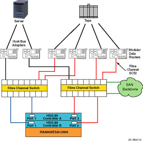
We recommend that you create a diagram for your own hardware configuration
to help you understand the hardware environment of your system.
Figure 1-1
shows a sample hardware configuration.
It includes the major hardware components
of a system that affect performance, such as the number of CPUs, host bus
adapters, network interface cards, Fibre Channel switches and connections,
and storage arrays.
Figure 1-1: Mapping Out Your Hardware Configuration
1.2 Performance Terminology and Concepts
System performance depends on an efficient utilization of system resources, which are the hardware and software components available to users or applications. A system must perform well under the normal workload exerted on the system by applications and users.
Because workloads change over time (for example, running additional applications), a system must be scalable, which refers to a system's ability to utilize additional hardware resources with a predictable impact on performance. Scalability can also refer to the ability of a system to absorb an increase in workload without a significant performance degradation.
A performance problem in a specific area of the configuration is called a bottleneck. A bottleneck can occur if the workload demands more from a resource than its capacity, which is the maximum theoretical throughput of a system resource.
Performance is often described in terms of two rates. Bandwidth is the rate at which an I/O subsystem or component can transfer bytes of data. Bandwidth is often called the transfer rate. Bandwidth is especially important for applications that perform large sequential data transfers.
Throughput is the rate at which an I/O subsystem or component can perform I/O operations. Throughput is especially important for applications that perform many small I/O operations.
Performance is also measured in terms of latency, which is the amount of time to complete a specific operation. Latency is often called delay. High-performance systems require a low latency time. I/O latency is measured in milliseconds; memory latency is measured in nanoseconds. Memory latency depends on the memory bank configuration and the amount of memory.
Disk performance is often described in terms of disk access time, which is a combination of the seek time, the amount of time for a disk head to move to a specific disk track, and the rotational latency, which is the amount of time for a disk to rotate to a specific disk sector.
A data transfer can consist of file-system data or raw I/O, which is I/O to a disk or disk partition that does not contain a file system. Raw I/O bypasses buffers and caches, and it may provide better performance, in some cases, than file system I/O. Raw I/O is often used by the operating system and by database application software.
Data transfers also have
different access patterns.
A
sequential access pattern
is an access pattern in which data is read from or written to contiguous (adjacent)
blocks on a disk.
A
random access pattern
is an access
pattern in which data is read from or written to blocks in different (usually
nonadjacent) locations on a disk.
1.3 Disk Storage Resources
Disk storage configurations vary greatly, so you must determine which configuration will meet the performance and availability needs of your applications and users.
Disk storage configurations can consist of single disks with traditional discrete disk partitions. However, you may want to use the Logical Storage Manager (LSM) to manage large amounts of disk storage. LSM enables you to set up a shared pool of storage, and also provides high-performance and high-availability features, such as RAID support.
Storage configurations can also include hardware RAID subsystems, which greatly expand the number of disks that can be connected to a single I/O bus and provide many high-performance and high-availability features, including RAID support and write-back caches. There are various types of hardware RAID subsystems that are suitable for different environments.
Host bus adapters, RAID controllers, and disks have various performance features and support Fibre Channel and different parallel Small Computer System Interface (SCSI) variants. Fibre Channel and SCSI are device and interconnect technologies that continue to evolve in terms of high performance, availability, and configuration flexibility. The following sections discuss disk storage resources in more detail:
See Section 1.3.1 for more information about RAID functionality.
See Section 1.3.2 for more information about SCSI.
See Section 1.3.3 for more information about Fibre Channel.
See Chapter 9 for more information about storage configurations.
You can use redundant array of independent disks (RAID) technology in a storage configuration for high performance and high data availability. You can obtain RAID functionality by using Logical Storage Manager (LSM) or a hardware-based RAID subsystem.
There are four primary RAID levels:
RAID0 — Also known as data or disk striping, RAID0 divides data into blocks and distributes the blocks across multiple disks in an array, which improves throughput. Striping does not provide disk data availability.
RAID1 — Also known as data or disk mirroring, RAID1 maintains identical copies of data on different disks in an array. Duplicating data on different disks provides high data availability and improves disk read performance. You can combine RAID1 with RAID0 to mirror striped data or disks.
RAID3 — A type of parity RAID, RAID3 divides data blocks and distributes the data across a disk array, providing parallel access to data and increasing bandwidth. RAID3 also provides data availability by placing redundant parity information on a separate disk, which is used to regenerate data if a disk in the array fails.
RAID5 — A type of parity RAID, RAID5 distributes data blocks across disks in an array. RAID5 allows independent access to data and can handle simultaneous I/O operations, which improves throughput. RAID5 provides data availability by distributing redundant parity information across the array of disks. The parity information is used to regenerate data if a disk in the array fails.
In addition, high-performance RAID controllers support dynamic parity RAID (also called adaptive RAID3/5), which combines the benefits of RAID3 and RAID5 to improve disk I/O performance for a wide variety of applications. Dynamic parity RAID dynamically adjusts, according to workload needs, between data transfer-intensive algorithms and I/O operation-intensive algorithms.
It is important to understand that RAID performance depends on the state of the devices in the RAID subsystem. There are three possible states:
Steady state (no failures)
Failure state (one or more disks have failed)
Recovery state (subsystem is recovering from failure)
Table 1-1
compares the performance features and
degrees of availability for the different RAID levels.
Table 1-1: RAID Level Performance and Availability Comparison
| RAID Level | Performance Feature | Degree of Availability |
| RAID0 (striping) | Balances I/O load and improves throughput | Lower than single disk |
| RAID1 (mirroring) | Improves read performance, but degrades write performance | Highest |
| RAID0+1 | Balances I/O load and improves throughput, but degrades write performance | Highest |
| RAID3 | Improves bandwidth, but performance may degrade if multiple disks fail | Higher than single disk |
| RAID5 | Improves throughput, but performance may degrade if multiple disks fail | Higher than single disk |
| Dynamic parity RAID (RAID3/5) | Improves bandwidth and throughput, but performance may degrade if multiple disks fail | Higher than single disk |
There are many variables to consider when choosing a RAID configuration:
Not all RAID products support all RAID levels.
For example, only high-performance RAID controllers support dynamic parity RAID.
RAID products provide different performance features.
For example, only RAID controllers support write-back caches and relieve the CPU of the I/O overhead.
Some RAID configurations are more cost-effective than others.
In general, LSM provides more cost-effective RAID functionality than hardware RAID subsystems. In addition, parity RAID provides data availability at a cost that is lower than RAID1 (mirroring), because mirroring n disks requires 2n disks.
Data recovery rates depend on the RAID configuration.
For example, if a disk fails, it is faster to regenerate data by using a mirrored copy than by using parity information. In addition, if you are using parity RAID, I/O performance declines as additional disks fail.
See
Chapter 9
for more information about RAID configurations.
1.3.2 SCSI Concepts
The most common type of SCSI is parallel SCSI, which supports SCSI variants that provide you with a variety of performance and configuration options. The SCSI variants are based on data path (narrow or wide), bus speed (Slow, Fast, Ultra, Ultra2, or Ultra3), and transmission method (single-ended or differential). These variants determine the bus bandwidth and the maximum allowable SCSI bus length.
Serial SCSI is the next generation of SCSI. Serial SCSI reduces parallel SCSI's limitations on speed, distance, and connectivity (number of devices on the bus), and also provides availability features like hot swap and fault tolerance.
Fibre Channel is an example of serial SCSI. A high-performance I/O bus that supports multiple protocols (SCSI, IPI, FIPS60, TCP/IP, HIPPI, and so forth), Fibre Channel is based on a network of intelligent switches. Link speeds are available up to 100 MB/sec in full-duplex mode.
The following sections describe parallel SCSI concepts in detail.
1.3.2.1 Data Paths
Disks, host bus adapters, I/O controllers, and storage enclosures support a specific data path. The data path and the bus speed determine the actual bandwidth for a bus. There are two data paths available:
Narrow data path
Specifies an 8-bit data path. The performance of this mode is limited. SCSI bus specifications restrict the number of devices on a narrow SCSI bus to eight.
Wide data path
Specifies a 16-bit data path for Slow, Fast SCSI, UltraSCSI, Ultra2, and Ultra3. This mode increases the amount of data that is transferred in parallel on the bus. SCSI bus specifications restrict the number of devices on a wide bus to 16.
Disks and host bus adapters that use a wide data path can provide nearly twice the bandwidth of disks and adapters that use a narrow data path. Wide devices can greatly improve I/O performance for large data transfers.
Most current disks support wide data paths.
Older disks have versions
that support wide and narrow data paths.
Devices with different data paths
(or transmission methods) cannot be directly connected on a single bus.
You
must use a SCSI signal converter (for example, a DWZZA or DWZZB) or an
UltraSCSI
extender (for example, a DWZZC or DWZZH [SCSI hub])
to connect devices with different data paths.
1.3.2.2 SCSI Bus Speeds
The SCSI bus speed, also called the transfer rate or bandwidth, is the number of transfers per second. Faster bus speeds provide the best performance. Both bus speed and the data path (narrow or wide) determine the actual bus bandwidth (number of bytes transferred per second).
Not all devices support all bus speeds. To set the bus speed on a host bus adapter, use either console commands or the Loadable Firmware Update (LFU) utility, depending on the type of adapter. See the TruCluster Server Software Version 5.1B QuickSpecs for information about SCSI device support.
Table 1-2
shows the available bus speeds.
Table 1-2: SCSI Bus Speeds
| Bus Speed | Maximum Transfer Rate (million transfers/sec) | Maximum Byte Transfer Rate: Narrow (MB/sec) | Maximum Byte Transfer Rate: Wide (MB/sec) |
| Ultra3 | 80 | 80 | 160 |
| Ultra2 | 40 | 40 | 80 |
| UltraSCSI | 20 | 20 | 40 |
| Fast SCSI | 10 | 10 | 20 |
| Slow | 5 | 5 | 10 |
HP's implementation of Ultra3 is compatible with and compliant to the Ultra 160/m implementation of the Ultra3 SCSI specification.
Fast SCSI, also called Fast10, is an extension to the SCSI-2 specification. It uses the fast synchronous transfer option, enabling I/O devices to attain high peak-rate transfers in synchronous mode.
UltraSCSI, also called
Fast20, is a high-performance,
extended version of SCSI-2 that reduces many performance and configuration
deficiencies of Fast SCSI.
Compared to Fast SCSI bus speed, UltraSCSI doubles
the bandwidth and configuration distances, but with no increase in cost.
UltraSCSI
also provides faster transaction times and faster, more accurate data analysis.
All UltraSCSI components are backward compatible with regular SCSI-2 components.
1.3.2.3 Transmission Methods
The transmission method for a bus refers to the electrical implementation of the SCSI specification. Supported transmissions methods include:
Single-ended (SE) SCSI
Used to connect devices that are usually located within the same cabinet. Single-ended SCSI usually requires short cable lengths.
A single-ended SCSI bus uses one data lead and one ground lead for the data transmission. A single-ended receiver looks at only the signal wire as the input. The transmitted signal arrives at the receiving end of the bus on the signal wire slightly distorted by signal reflections. The length and loading of the bus determine the magnitude of this distortion. Therefore, the single-ended transmission method is economical, but it is more susceptible to noise than the differential transmission method and requires short cables.
Differential SCSI
Used to connect devices that are up to 25 meters apart.
A differential SCSI bus uses two wires to transmit a signal. The two wires are driven by a differential driver that places a signal on one wire (+SIGNAL) and another signal that is 180 degrees out of phase (-SIGNAL) on the other wire. The differential receiver generates a signal output only when the two inputs are different. Because signal reflections are virtually the same on both wires, they are not seen by the receiver, which notices only differences on the two wires. The differential transmission method is less susceptible to noise than single-ended SCSI and enables you to use long cables.
You cannot directly connect SE and differential devices on the same bus. To connect SE and differential devices on the same bus you must use an UltraSCSI extender.
Low Voltage Differential (LVD) SCSI
Same as differential SCSI, but uses low voltage and you can directly connect SE and LVD SCSI drives on the same SCSI bus.
When SE and LVD SCSI devices are connected on the same SCSI bus, performance is limited to SE SCSI operation (40 MB/sec) for all devices on the SCSI bus (for that particular SCSI channel). According to the rules of SCSI, to maintain a true LVD SCSI bus and its associated performance, only LVD SCSI drives can be on the same LVD SCSI channel. However, this does not prevent the support of dedicated SE channels and dedicated LVD channels, all on a single array controller.
Ultra2 and Ultra3 devices operate on the LVD electrical platform. When Ultra2 and Ultra3 devices are connected on the same Ultra3 SCSI bus, the Ultra2 devices will transfer data up to 80 MB/sec, while the Ultra3 devices will transfer data up to 160 MB/sec. If the SCSI bus is only capable of supporting Ultra2, all LVD devices will have a maximum transfer of 80 MB/sec.
1.3.2.4 Extending UltraSCSI Bus Segments
UltraSCSI devices can be either single-ended or differential. Because of UltraSCSI's high bus speed, single-ended UltraSCSI signals cannot maintain their strength and integrity over the same distance as single-ended Fast SCSI signals. Therefore, UltraSCSI technology uses bus segments and bus extenders so that systems and storage can be configured over long distances.
An UltraSCSI bus extender joins two bus segments together without any impact on SCSI protocol. A bus segment is defined as an unbroken electrical path consisting of conductors (in cables or backplanes) and connectors. Every UltraSCSI bus segment must have two terminators, one at each end of the bus segment. Therefore, an UltraSCSI bus segment corresponds to an entire bus in Fast SCSI. The SCSI domain is the collection of SCSI devices on all the bus segments. As with a Fast SCSI bus, an UltraSCSI bus segment can only support devices of the same type (single-ended or differential).
Although UltraSCSI components allow an UltraSCSI domain to extend for
longer distances than a Fast SCSI bus, there are still limits.
Also, because
the use of bus expanders allows UltraSCSI domains to look like a tree instead
of a straight line, the concept of bus length must be replaced with the concept
of the UltraSCSI domain diameter.
1.3.2.5 SCSI Bus Length and Termination
There is a limit to the length of the cables in a SCSI bus. The maximum cable length depends on the bus speed and the transmission method (single-ended or differential). The total cable length for a physical bus or UltraSCSI bus segment is calculated from one terminated end to the other.
In addition, each SCSI bus or bus segment must be terminated only at each end. Improper bus termination and lengths are a common cause of bus malfunction.
If you are using devices that have the same transmission method and data path (for example, wide and differential), a bus will consist of only one physical bus (or multiple bus fragments in the case of UltraSCSI). If you have devices with different transmission methods, you will have both single-ended and differential physical buses or bus segments, each of which must be terminated only at both ends and adhere to the rules on bus length.
Table 1-3
shows the maximum bus lengths for different
bus speeds and transmission methods.
Table 1-3: SCSI Bus and Segment Lengths
| Bus Speed | Transmission Method | Maximum Bus or Segment Length |
| Slow | Single-ended | 6 meters |
| Fast | Single-ended | 3 meters |
| Fast | Differential | 25 meters |
| Ultra | Differential | 25 meters |
| Ultra | Single-ended | 1.5 meters (daisy-chain configuration in which devices are spaced less than 1 meter apart) |
| Ultra | Single-ended | 4 meters (daisy-chain configuration in which devices are spaced more than 1 meter apart) |
| Ultra | Single-ended | 20 meters (point to point configuration in which devices are only at the ends of the bus segment) |
Note that the total length of a physical bus must include the amount
of cable that is located inside each system and disk storage shelf.
This length
varies, depending on the device.
For example, the length of cable inside a
BA350, BA353, or BA356 storage shelf is approximately 1.0 meter.
1.3.3 Fibre Channel
Fibre Channel supports multiple protocols over the same physical interface. Fibre Channel is primarily a protocol-independent transport medium; therefore, it is independent of the function for which you use it.
Tru64 UNIX uses the Fibre Channel Protocol (FCP) for SCSI to use Fibre Channel as the physical interface.
Fibre Channel, with its serial transmission method, overcomes the limitations of parallel SCSI by providing:
Support for multiple protocols
Better scalability
Improved reliability and availability
Fibre Channel uses an extremely high-transmit clock frequency to achieve the high data rate. Using optical fiber transmission lines allows the high-frequency information to be sent up to 40 kilometers (24.85 miles), which is the maximum distance between transmitter and receiver. Copper transmission lines may be used for shorter distances.
The following sections describe Fibre Channel in more detail:
Fibre Channel topologies (Section 1.3.3.1)
Fibre Channel topology comparison (Section 1.3.3.2)
Zoning (Section 1.3.3.3)
1.3.3.1 Fibre Channel Topologies
Fibre Channel supports three different interconnect topologies:
Point-to-point (Section 1.3.3.1.1)
Fabric (Section 1.3.3.1.2)
Arbitrated loop (Section 1.3.3.1.3)
Note
Although you can interconnect an arbitrated loop with the fabric, hybrid configurations are not currently supported; therefore, those configurations are not discussed in this manual.
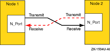
1.3.3.1.1 Point-to-Point Topology
The point-to-point topology is the simplest Fibre Channel topology. In a point-to-point topology, one N_Port is connected to another N_Port by a single link.
Because all frames transmitted by one N_Port are received by the other N_Port, and in the same order in which they were sent, frames require no routing.
Figure 1-2
shows an example point-to-point topology.
Figure 1-2: Point-to-Point Topology
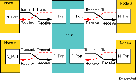
The fabric topology provides more connectivity than point-to-point topology. The fabric topology can connect up to 224 ports.
The fabric examines the destination address in the frame header and routes the frame to the destination node.
A fabric may consist of a single switch, or there may be several interconnected switches (up to three interconnected switches are supported). Each switch contains two or more fabric ports (F_Ports) that are internally connected by the fabric switching function, which routes the frame from one F_Port to another F_Port within the switch. Communication between two switches is routed between two expansion ports (E_Ports).
When an N_Port is connected to an F_Port, the fabric is responsible for the assignment of the Fibre Channel address to the N_Port attached to the fabric. The fabric is also responsible for selecting the route a frame will take, within the fabric, to be delivered to the destination.
When the fabric consists of multiple switches, the fabric can determine an alternate route to ensure that a frame gets delivered to its destination.
Figure 1-3
shows an example fabric topology.
Figure 1-3: Fabric Topology
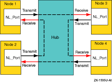
1.3.3.1.3 Arbitrated Loop Topology
In an arbitrated loop topology, frames are routed around a loop set up by the links between the nodes. The hub maintains loop continuity by bypassing a node when the node or its cabling fails, when the node is powered down, or when the node is removed for maintenance. The hub is transparent to the protocol. It does not consume any Fibre Channel arbitrated loop addresses so it is not addressable by a Fibre Channel arbitrated loop port.
The nodes arbitrate to gain control (become master) of the loop. After a node becomes the master, the nodes select (by way of setting bits in a bitmask) their own Arbitrated Loop Physical Address (AL_PA). The AL_PA is used to address nodes on the loop. The AL_PA is dynamic and can change each time the loop is initialized, a node is added or removed, or at any other time that an event causes the membership of the loop to change. When a node is ready to transmit data, it transmits Fibre Channel primitive signals that include its own identifying AL_PA.
In the arbitrated loop topology, a node port is called an NL_Port (node loop port), and a fabric port is called an FL_Port (fabric loop port).
Figure 1-4
shows an example of an arbitrated
loop topology.
Figure 1-4: Arbitrated Loop Topology
1.3.3.2 Fibre Channel Topology Comparison
This section compares and contrasts the fabric and arbitrated loop topologies, and describes why you might choose to use them.
When compared with the fabric (switched) topology, arbitrated loop is a lower cost, and lower performance, alternative. Arbitrated loop reduces Fibre Channel cost by substituting a lower-cost, often nonintelligent and unmanaged hub, for a more expensive switch. The hub operates by collapsing the physical loop into a logical star. The cables, associated connectors, and allowable cable lengths are similar to those of a fabric. Arbitrated loop supports a theoretical limit of 127 nodes in a loop. Arbitrated loop nodes are self-configuring and do not require Fibre Channel address switches.
Arbitrated loop provides reduced cost at the expense of bandwidth; all nodes in a loop share the bandwidth (100 MB/sec per loop), and bandwidth degrades slightly as nodes and cables are added. Nodes on the loop see all traffic on the loop, including traffic between other nodes. The hub can include port-bypass functions that manage movement of nodes on and off the loop. For example, if the port bypass logic detects a problem, the hub can remove that node from the loop without intervention. Data availability is then preserved by preventing the down time associated with node failures, cable disconnections, and network reconfigurations. However, traffic caused by node insertion and removal, errors, and so forth, can cause temporary disruption on the loop.
Although the fabric topology is more expensive, it provides both increased connectivity and higher performance; switches provide a full-duplex 100 (200) MB/sec point-to-point connection to the fabric. Switches also provide improved performance and scaling because nodes on the fabric see only data destined for themselves, and individual nodes are isolated from reconfiguration and error recovery of other nodes within the fabric. Switches can provide management information about the overall structure of the Fibre Channel fabric, which may not be the case for an arbitrated loop hub.
Table 1-4
compares the fabric and arbitrated
loop topologies.
Table 1-4: Fibre Channel Fabric and Arbitrated Loop Comparison
| When to Use Arbitrated Loop | When to Use Fabric |
| In clusters of up to two members | In clusters of more than two members |
| In applications where low total solution cost and simplicity are key requirements | In multinode cluster configurations when possible temporary traffic disruption due to reconfiguration or repair is a concern |
| In applications where the shared bandwidth of an arbitrated loop configuration is not a limiting factor | In high bandwidth applications where a shared arbitrated loop topology is not adequate |
| In configurations where expansion and scaling are not anticipated | In cluster configurations where expansion is anticipated and requires performance scaling |
This section provides a brief overview of zoning.
A zone is a logical subset of the Fibre Channel devices that are connected to the fabric. Zoning allows partitioning of resources for management and access control. In some configurations, it may provide for more efficient use of hardware resources by allowing one switch to serve multiple clusters or even multiple operating systems. Zoning entails splitting the fabric into zones, where each zone is essentially a virtual fabric.
Zoning may be used:
When you want to set up barriers between systems of different operating environments or uses; for example, to allow two clusters to utilize the same switch.
To create test areas that are separate from the rest of the fabric.
To provide better utilization of a switch by reducing the number of unused ports.
Note
Any initial zoning must be made before connecting the host bus adapters and the storage to the switches. However, after zoning is configured, changes can be made dynamically.
1.3.3.3.1 Switch Zoning Versus Selective Storage Presentation
Switch zoning and the selective storage presentation (SSP) feature of the HSG80 controllers have similar functions.
Switch zoning controls which servers can communicate with each other and each storage controller host port. SSP controls which servers will have access to each storage unit.
Switch zoning controls access at the storage system level; SSP controls access at the storage unit level.
The following configurations require zoning or selective storage presentation:
When you have a TruCluster Server cluster in a storage array network (SAN) with other standalone systems (UNIX or non-UNIX), or other clusters.
Any time you have Windows NT or Windows 2000 in the same SAN with Tru64 UNIX. (Windows NT or Windows 2000 must be in a separate switch zone.)
The SAN configuration has more than 64 connections to an RA8000, ESA12000, MA6000, MA8000, or EMA12000.
The use of selective storage presentation is the preferred way to control
access to storage (so zoning is not required).
1.3.3.3.2 Types of Zoning
There are two types of zoning, soft and hard:
Soft zoning is a software implementation that is based on the Simple Name Server (SNS) enforcing a zone. Zones are defined by either the node or port World Wide Names (WWN), or the domain and port numbers in the form of D,P, where D is the domain and P is the physical port number on the switch.
A host system requests a list of all adapters and storage controllers that are connected to the fabric. The name service provides a list of all ports that are in the same zone or zones as the requesting host bus adapter.
Soft zoning only works if all hosts honor it; it does not work if a host is not programmed to allow for soft zoning. For example, if a host tries to access a controller that is outside the zone, the switch does not prevent the access.
Tru64 UNIX honors soft zoning and does not attempt to access devices outside the zone.
If you have used the WWN to define the zone and replace a KGPSA host bus adapter, you must modify the zone configuration and SSP because the node WWN has changed.
With hard zoning, zones are enforced at the physical level across all fabric switches by hardware blocking of the Fibre Channel frames. Hardware zone definitions are in the form of D,P, where D is the domain and P is the physical port number on the switch. An example might be 1,2 for switch 1, port 2.
If a host attempts to access a port that is outside its zone, the switch hardware blocks the access.
You must modify the zone configuration when you move any cables from one port to another within the zone.
If you want to guarantee that there is no access outside any zone, either use hard zoning, or use operating systems that state they support soft zoning.
Table 1-5
lists the types of zoning that
are supported on each of the supported Fibre Channel switches.
Table 1-5: Type of Zoning Supported by Switches
| Switch Type | Type of Zoning Supported |
| DS-DSGGA | Soft |
| DS-DSGGB | Soft and Hard |
| DS-DSGGC | Soft and Hard |
Figure 1-5
shows a sample configuration using zoning.
This configuration consists of two independent zones with each zone containing
an independent cluster.
Figure 1-5: A Simple Zoned Configuration
For information on setting up zoning, see the SAN Switch Zoning documentation that is provided with the switch.
See the
Cluster Hardware Configuration
manual for more information.
1.3.3.4 Cascaded Switches
Multiple switches may be connected to each other to form a network of switches, or cascaded switches.
A cascaded switch configuration, which allows for network failures up to and including the switch without losing a data path to a SAN connected node, is called a mesh or meshed fabric.
Figure 1-6
shows an example meshed resilient fabric
with four cascaded interconnected switches.
This configuration will tolerate
multiple data path failures, and is an NSPOF (no single point of failure)
configuration.
Figure 1-6: Meshed Resilient Fabric with Four Cascaded Switches
Note
If you lose an ISL, the communication can be routed through another switch to the same port on the other controller. This can constitute the maximum allowable two hops.
See the
Cluster Hardware Configuration
manual for more information on Fibre
Channel.
1.4 Network Resources
Systems support various networks and network adapters that provide different performance features. For example, an Asynchronous Transfer Mode (ATM) high-performance network is ideal for applications that need the high speed and the low latency (switched, full-duplex network infrastructure) that ATM networks provide.
In addition, you can configure multiple network adapters or use NetRAIN to increase network access and provide high network avialability.
Your system is connected to the network through a Network Interface Card (NIC) (which is also called a network interface or network adapter). End systems or hosts can have the following interface options:
Single interface in a subnet
Multiple interfaces in a subnet
Multiple interfaces with automatic failover (NetRAIN)
Multiple aggregated interfaces (link aggregation)
Routers typically have multiple interfaces, each connected to a different
subnet.
Figure 1-7
shows a network with two hosts, Host A
and Host B, each with a single network interface in a subnet.
Figure 1-7: Single Interface Configuration
The following sections discuss network resources that are important
to improve system performance.
1.4.1 Network Subsystem
Most resources used by the network subsystem are allocated and adjusted dynamically; however, there are some tuning guidelines that you can use to improve performance, particularly with systems that are Internet servers, including Web, proxy, firewall, and gateway servers.
Network performance is affected when the supply of resources is unable to keep up with the demand for resources. The following two conditions can cause this to occur:
A problem with one or more hardware or software network components
A workload (network traffic) that consistently exceeds the capacity of the available resources, although everything appears to be operating correctly
Neither of these problems are network tuning issues.
In the
case of a problem on the network, you must isolate and eliminate the problem.
In the case of high network traffic (for example, the hit rate on a Web server
has reached its maximum value while the system is 100 percent busy), you must
either redesign the network and redistribute the load, reduce the number of
network clients, or increase the number of systems handling the network load.
1.4.2 Using Redundant Networks
Network connections may fail because of a failed network interface or a problem in the network itself. You can make the network connection highly available by using redundant network connections. If one connection becomes unavailable, you can still use the other connection for network access. Whether you can use multiple networks depends on the application, network configuration, and network protocol.
You can also use NetRAIN (redundant array of independent network adapters) to configure multiple interfaces on the same LAN segment into a single interface, and to provide failover support for network adapter and network connections. One interface is always active while the other interfaces remain idle. If the active interface fails, an idle interface is brought on line within less than 10 seconds.
NetRAIN supports only Ethernet and FDDI, see Section 1.4.3 for more information about NetRAIN.
See
nr(7)1.4.3 NetRAIN
The Redundant Array of Independent Network Adaptors (NetRAIN) interface provides a mechanism to protect against certain kinds of network connectivity failures.
NetRAIN integrates multiple network interfaces on the same local area
network (LAN) segment into a single virtual interface called a NetRAIN set.
One network interface in the set is always active while the others remain
idle.
If the active interface fails, one of the idle set members comes on
line with the same IP address within an adjustable failover time period.
Figure 1-8
shows Host A with three interfaces that are part
of a NetRAIN set.
The NetRAIN virtual interface is assigned the address 16.1.1.1.
Figure 1-8: Mulitple Interfaces
NetRAIN monitors the status of its network interfaces with the Network
Interface Failure Finder (NIFF), a tool used to detect and report possible
network failures.
This tool can be used independently of NetRAIN.
For more
information about NIFF, see
NIFF(7)1.4.4 Routing
All systems (hosts and routers) connected to a network must be configured to support network routing in order to communicate with other systems on other networks. A route is the path a packet takes through a network from one system to another. As such it enables you to communicate with other systems on other networks. Routes are stored on each system in the routing tables or routing database. Each route entry consists of the following:
A destination address (either a network or a host)
The address of the next hop from your system to the destination
The address of your system on the network if the route is through an interface
A network interface (for example,
tu0
and
fta0)
Metrics (for example, hop count and MTU)
Additional routes might be added to your routing tables based on Internet
Control Message Protocol (ICMP) redirect messages.
These are messages from
routers to hosts that tell the host to forward traffic to another router on
the local network.
1.4.5 LAG Interface
Link aggregation (LAG) interfaces provide higher availability, fault tolerance, and load sharing on systems that contain multiple network adapters. Link aggregation, or trunking, also enables administrators to combine one or more physical Ethernet NICs and create a single logical link. (Upper-layer software sees this link aggregation group as a single logical interface.) The single logical link can carry traffic at higher data rates than a single interface because the traffic is distributed across all of the physical ports that make up the link aggregation group.
Using link aggregation provides the following capabilities:
Increased network bandwidth — The increase is incremental based on the number and type of ports, or NICs, added to the link aggregation group.
Fault tolerance — If a port in a link aggregation group fails, the software detects the failure and reroutes traffic to the other available ports. This capability is available for DEGPA (alt) and DE60x (ee) devices only.
Load sharing — A link aggregation group performs load sharing of both inbound and outbound traffic. When transmitting packets, the system uses a load distribution algorithm to determine on which attached port to transmit the packets.
You can use a link aggregation group virtual interface for the following
point-to-point connections: server-to-server and server-to-switch.
For more
information see the
Network Administration: Connections
guide.
1.5 File System Resources
File-system tuning is important for the Advanced File System (AdvFS)
and the Network File System (NFS).
In general, file-system tuning will improve
the performance of I/O-intensive user applications.
The following sections
discuss the file system resources for AdvFS, UNIX File System (UFS), and NFS.
1.5.1 Using AdvFS
The Advanced File System (AdvFS) file system differs from the traditional UNIX File System (UFS). With AdvFS you can modify your system configuration at any time without shutting down the system. Because AdvFS with AdvFS utilities supports a multivolume file system, you can easily add or remove storage as your system requirements change. In addition, Logical Storage Manager (LSM) volumes and storage area networks (SANs) can be used for AdvFS storage.
In contrast, the UFS model is rigid.
Each disk (or disk partition) contains
a single file system.
The directory hierarchy layer of UFS is bound tightly
to the physical storage layer.
When a file system becomes full, this tight
binding makes it impossible to move selected files onto another disk without
changing the full pathnames of those files.
The task of dividing a logical
directory into directory subtrees and mapping the subtrees onto separate disks
requires careful consideration.
Even with extensive planning, adjustments
to the directory structure are limited with the UFS model.
1.5.1.1 Using the UBC
Caching improves performance when data is reused frequently. AdvFS uses a dynamic memory cache called the Unified Buffer Cache (UBC) to manage file metadata and user data.
By using the UBC for caching, AdvFS can maintain file data in memory as long as memory is available. If other system resources require some of the memory in use by the file system cache, the UBC can reclaim some of the memory used by the file system and reissue the needed memory to the resource requiring it.
Because AdvFS uses the UBC to control caching, the cache is tuned with the UBC tunable parameters. These include:
Variables that modify the maximum percentage of physical memory that the UBC can use at one time.
The percentage of pages that must be dirty before the UBC starts writing them to disk.
The maximum amount of memory allocated to the UBC that can be used to cache a single file.
See
Chapter 11
for the guidelines to modify these
parameters.
1.5.2 Using NFS
The network file system (NFS) allows users to access files transparently across networks. The NFS supports a spectrum of network topologies, from small and simple networks to large and complex networks. The NFS shares the Unified Buffer Cache (UBC) with the virtual memory subsystem and local file systems.
File-system tuning is important for NFS because processing NFS requests consumes the majority of CPU and wall clock time. Ideally, the UBC hit rate should be high. Increasing the UBC hit rate can require additional memory or a reduction in the size of other file-system caches.
NFS uses a simple stateless protocol, which requires that each client request be complete and self-contained and that the server completely process each request before sending an acknowledgment back to the client.
Improving performance on a system that is used only for serving NFS differs from tuning a system that is used for general timesharing, because an NFS server runs only a few small user-level programs, which consume few system resources. There is minimal paging and swapping activity, so memory resources should be focused on caching file system data.
See
Chapter 5
and
Chapter 10
for more
information on NFS tuning.
1.6 Memory Resources
Sufficient memory resources are vital to system performance. Configurations running CPU and memory-intensive applications often require very-large memory (VLM) systems that utilize 64-bit architecture, multiprocessing, and at least 2 GB of memory. Very-large database (VLDB) systems are VLM systems that also utilize complex storage configurations.
The total amount of physical memory is determined by the capacity of the memory boards installed in your system. The virtual memory (vm) subsystem tracks and manages this memory in 8-KB portions called pages, distributing them among the following areas:
Static wired memory
Allocated at boot time and used for operating system data and text and for system tables, static wired memory is also used by the metadata buffer cache, which holds recently accessed UNIX File System (UFS) and CD-ROM File System (CDFS) metadata.
Dynamically wired memory
Dynamically wired memory is used for dynamically allocated data structures,
such as system hash tables.
User processes also allocate dynamically wired
memory for address space by using virtual memory locking interfaces, including
the
mlock
function.
The amount of dynamically wired memory
varies according to the demand.
The
vm
subsystem attribute
vm_syswiredpercent
specifies the maximum amount of memory that a
user process can wire (by default, this is 80 percent of physical memory).
Physical memory for processes and data caching
Physical memory that is not wired is referred to as pageable memory. It is used for processes' most-recently accessed anonymous memory (modifiable virtual address space) and file-backed memory (memory that is used for program text or shared libraries). Pageable memory is also used to cache the most-recently accessed UFS file system data for reads and writes and for page faults from mapped file regions, in addition to AdvFS metadata and file data. The virtual memory subsystem allocates physical pages according to the process and file system demand.
Figure 1-9
shows the division of physical memory.
Figure 1-9: Physical Memory Usage
Physical memory is a resource that
all active processes use.
Often there is not enough physical memory to accommodate
all active processes on the system.
To provide more physical memory, the
vm
subsystem monitors the amount of available physical memory and
might transfer pages to a secondary memory device called a
swap
device.
A swap device is a block device in a configured section
of a disk.
The kernel retrieves pages from a swap device on demand when a
process references the pages.
This memory management policy is called
paging.
Under heavy loads, an entire process might be transferred to a swap device. A process called the swapper manages the transfer of pages between physical memory and a swap device. This memory management policy is called swapping.
See
Chapter 12
for more information on how to tune attributes
that relate to paging and swapping.
1.6.2 Caching Data
The kernel caches (temporarily stores) in memory recently accessed data. Caching data is effective because data is frequently reused and it is much faster to retrieve data from memory than from disk. When the kernel requires data, it checks if the data was cached. If the data was cached, it is returned immediately. If the data was not cached, it is retrieved from disk and cached. File system performance is improved if the cached data is later reused.
Cached data can be information about a file, user or application data, or metadata, which is data that describes an object for example, a file. The following list identifies the types of data that are cached:
A file name and its corresponding
vnode
is cached in the namei cache (Section 11.1.2).
UFS user and application data and AdvFS user and application data and metadata are cached in the Unified Buffer Cache (UBC) (Section 11.1.3).
UFS metadata is cached in the metadata buffer cache (Section 11.1.4).
AdvFS open file information is cached in access structures (Section 11.1.5).
CPUs support different processor speeds and onboard cache sizes. In addition, you can choose single-CPU systems or multiprocessor systems, which allow two or more processors to share common physical memory. Environments that are CPU-intensive, such as large database environments, require multiprocessing systems to handle the workload.
An example of a multiprocessing system is a symmetrical multiprocessing (SMP) system, in which the CPUs execute the same version of the operating system, access common memory, and execute instructions simultaneously.
When programs are executed, the operating system moves
data and instructions through CPU caches, physical memory, and disk swap space.
Accessing the data and instructions occurs at different speeds, depending
on the location.
Table 1-6
describes the various hardware
resources.
Table 1-6: Memory Management Hardware Resources
| Resource | Description |
| CPU chip caches | Various internal caches reside in the CPU chip. They vary in size, up to a maximum of 64 KB, depending on the processor. These caches include the translation look aside buffer, the high-speed internal virtual-to-physical translation cache, the high-speed internal instruction cache, and the high-speed internal data cache. |
| Secondary cache | The secondary direct-mapped physical data cache is external to the CPU, but usually resides on the main processor board. Block sizes for the secondary cache vary from 32 bytes to 256 bytes (depending on the type of processor). The size of the secondary cache ranges from 128 KB to 8 MB. |
| Tertiary cache | The tertiary cache is not available on all Alpha CPUs; otherwise, it is identical to the secondary cache. |
| Physical memory | The actual amount of physical memory varies. |
| Swap space | Swap space consists of one or more disks or disk partitions (block special devices). |
The hardware logic and the Privileged Architecture Library (PAL) code control much of the movement of addresses and data among the CPU cache, the secondary and tertiary caches, and physical memory. This movement is transparent to the operating system.
Movement between caches and physical memory is significantly faster than movement between disk and physical memory, because of the relatively slow speed of disk I/O. Applications should utilize caches and avoid disk I/O operations whenever possible.
Figure 1-10
shows how instructions and data are moved
among various hardware components during program execution, and shows the
machine cycles needed to access data and instructions from the hardware locations.
Figure 1-10: Moving Instructions and Data Through the Memory Hardware
For more information on the CPU, secondary cache, and tertiary cache, see the Alpha Architecture Reference Manual.
There are several ways that you can optimize CPU performance.
You can
reschedule processes or use the Class Scheduler to allocate a percentage of
CPU time to a task or application.
This allows you to reserve a majority of
CPU time for important processes, while limiting CPU usage by less critical
processes.
See
Section 13.2.2
for more information.
1.8 Identifying a Resource Model for Your Workload
Before you can plan or tune a configuration, you must identify a resource model for your workload. That is, you must determine if your applications are memory-intensive or CPU-intensive, and how they perform disk and network I/O. This information will help you to choose the configuration and tuning guidelines that are appropriate for your workload.
For example, if a database server performs large sequential data transfers, choose a configuration that provides high bandwidth. If an application performs many disk write operations, you may not want to choose a RAID1 (mirrored) configuration.
Use
Table 1-7
to help you determine the resource model
for your workload and identify a possible configuration solution for each
model.
Table 1-7: Resource Models and Possible Configuration Solutions
| Resource Model | Configuration Solution |
| CPU-intensive | Multiprocessing system, fast CPUs, or hardware RAID subsystem |
| Memory-intensive | VLM system or large onboard CPU cache |
| Requires large amount of disk storage | System with a large I/O capacity, LSM, or hardware RAID subsystem |
| Requires low disk latency | Solid-state disks, fast disks, RAID array, or Fibre Channel |
| Requires high throughput | Solid-state disks, high-performance SCSI adapters, striping, RAID5, or dynamic parity RAID (adaptive RAID3/5) |
| Requires high bandwidth | Solid-state disks, high-performance adapters, wide devices, RAID3, or dynamic parity RAID |
| Performs many large sequential data transfers | High-performance disks, wide devices, striping, parity RAID |
| Performs many small data transfers | RAID5 |
| Issues predominantly read transfers | Mirroring, RAID5, or striping |
| Issues predominantly write transfers | Prestoserve or write-back cache |
| Performs many network operations | Multiple network adapters, NetRAIN, or high-performance adapters |
| Application must be highly available | Cluster |
| Data must be highly available | Mirroring (especially across different buses) or parity RAID |
| Network I/O-intensive | Multiple network adapters or NetRAIN |
1.9 Most Commonly Tuned Subsystems
This manual describes how to tune many subsystem attributes. We recommend tuning only those attributes that are specific to your system and performance problem. The five most commonly tuned subsystems are:
Virtual Memory (vm)
new_wire_method
(Section 4.4.1.1)
rad_gh_regions
(Section 4.4.1.2)
gh_chunks
(Section 4.4.1.2.2)
ubc_maxpercent
(Section 4.4.1.3)
ubc_borrowpercent
(Section 4.4.1.4)
vm_ubcseqstartpercent
(Section 4.4.1.6)
vm_ubcdirtypercent
(Section 4.4.1.7)
vm_swap_eager
(Section 4.4.1.8)
Interprocess Communication (ipc)
ssm_threshold
(Section 4.4.4.1)
shm_max
(Section 4.4.4.2)
shm_min
(Section 4.4.4.3)
shm_mni
(Section 4.4.4.4)
shm_seg
(Section 4.4.4.5)
Process (proc)
per_proc_stack_size
(Section 4.4.6.1)
max_per_proc_stack_size
(Section 4.4.6.2)
per_proc_data_size
(Section 4.4.6.3)
max_per_proc_data_size
(Section 4.4.6.4
and
Section 6.2.2.4)
per_proc_address_space
(Section 4.4.6.5)
max_per_proc_address_space
(Section 4.4.6.6
and
Section 6.2.2.5)
max_proc_per_user
(Section 4.4.6.7
and
Section 6.2.2.2)
max_threads_per_user
(Section 4.4.6.8
and
Section 6.2.2.3)
maxusers
(Section 4.4.6.9
and
Section 6.2.2.1)
Internet (inet)
udp_sendspace
(Section 4.4.5.1)
udp_recvspace
(Section 4.4.5.2)
udp_unserreserved
(Section 4.4.5.3)
tcbhashsize
(Section 6.2.1.1)
pmtu_enabled
(Section 6.2.1.2)
ipport_userreserved
(Section 6.2.1.3)
Socket (socket)
somaxconn
(Section 6.2.3.1)
sominconn
(Section 6.2.3.2)
sbcompress-threshold
(Section 6.2.3.3)
This manual describes how to tune your system by application type and component. Before tuning your system, you need to understand your system hardware configuration (see Section 1.1 for more information). The most commonly tuned subsystems are mentioned throughout this manual, but only tune those attributes that are related to your performance problem.
The following chapters describe which attributes to tune for improving system performance:
Tuning by Application Type (Part 2):
Tuning by Component (Part 3):
For more information on subystem attributes, see
sys_attrs(5)