 |
HP OpenVMS systems documentation |
| Previous | Contents | Index |
Removing IPv6 from an interface removes the IPv6 configuration associated with the interface, including all IPv6 addresses and IPv6 routes through the interface. To remove IPv6 from an interface, use the ifconfig command with the following syntax:
$ ifconfig interface -ipv6 |
For example, to remove IPv6 from Ethernet interface WE0, enter the following:
$ ifconfig "WE0" -ipv6 |
To create a configured tunnel, use the iptunnel command in the following format:
iptunnel create remote-tunnel-IPv4address |
For example, to create a tunnel to remote system 16.20.136.47, enter the following command:
$ iptunnel create 16.20.136.47 |
To initialize the tunnel for IPv6 operation, enter the following command:
$ ifconfig "IT0" ipv6 up |
OpenVMS interface names must be in uppercase. When you enter them with UNIX management commands at the DCL prompt, you must enclose the name of the interface in quotation marks. |
To add or assign an IPv6 prefix to an interface and to direct the kernel to automatically append the interface identifier, use the ifconfig command with the following syntax:
ifconfig interface inet6 ip6prefix prefix |
The following example assigns the address dec:2::0a00:2bff:fe12:3456 to interface WE0 (the interface ID is 0a00:2bff:fe12:3456 ):
$ ifconfig "WE0" inet6 ip6prefix dec:2::/64 |
The ip6prefix parameter directs the kernel to automatically append the interface identifier to the address prefix.
To add or assign a full IPv6 address to an interface manually, use the ifconfig command with the following syntax:
ifconfig interface inet6 ipv6address |
The following example assigns the address dec:2::1 to interface WE0:
$ ifconfig "WE0" inet6 dec:2::1 |
For IPv6 hosts, the TCPIP$ND6HOST process configures interface prefixes automatically, depending on the contents of router advertisements. For IPv6 routers, the TCPIP$IP6RTRD process configures interface prefixes automatically, depending on the contents of the SYS$SYSTEM:TCPIP$IP6RTRD.CONF file. |
To delete an IPv6 address from an interface manually, use the ifconfig command with the following syntax:
ifconfig interface inet6 delete ipv6address |
For example:
$ ifconfig "WE0" inet6 delete dec:2::1 |
OpenVMS interface names must be in uppercase. When you enter them with UNIX management commands at the DCL prompt, you must enclose the name of the interface in quotation marks. |
To add a default router, use the route command with the following syntax:
route add -inet6 default ipv6address -I interface |
For example:
$ route add -inet6 default fe80::0a00:2bff:fe12:3456 -"I" "WE0" |
UNIX flags and OpenVMS interface names are case sensitive. When entering UNIX management commands at the DCL prompt, you must enclose uppercase UNIX flags and OpenVMS interface names in quotation marks. |
To delete a default router, use the route command with the following syntax:
route delete -inet6 default ipv6address -I interface |
For example:
$ route delete -inet6 default fe80::0a00:2bff:fe12:3456 -"I" "WE0" |
For IPv6 hosts, the TCPIP$ND6HOST process performs the add and delete route operations automatically, depending on the contents of router advertisements. See Section 2.1.1 for more information about TCPIP$ND6HOST. |
After you manually add an address prefix to an interface, you also can add a static route so that traffic to other hosts with the same prefix is sent directly to the destination rather than through a router. For example, if the prefix DEC:5::/64 has been added to the Ethernet interface WE0, which has been initialized with the link-local address fe80::0a00:2bff:fe12:3456 , the following command adds a route to neighboring hosts with the same prefix:
$ route add -inet6 dec:5::/64 fe80::0a00:2bff:fe12:3456 -interface |
This command specifies that destinations with prefix dec:5::0/64 are reachable through the interface with address fe80::0a00:2bff:fe12:3456 . That is, dec:5::0/64 is an on-link prefix.
For IPv6 hosts, the TCPIP$ND6HOST process automatically adds on-link prefixes based on the contents of router advertisements. See Section 2.1.1 for more information about TCPIP$ND6HOST. |
To monitor your network, use the following UNIX-style commands:
UNIX flags are case sensitive. When using an uppercase flag you must enclose it with quotation marks to get the expected behavior. OpenVMS interface names are case sensitive. The name of the interface must be enclosed in quotation marks. |
The following sections describe each command.
4.3.1 ping Command
You can test access to internet network hosts with the ping command. The ping command accepts an IPv4 address, an IPv6 address, or a node name on the command line. The following sample command specifies an IPv6 address:
$ ping -c 2 5F00:2100:108C:4000:8C40:800:2B2D:2B2

PING (5F00:2100:108C:4000:8C40:800:2B2D:2B2): 56 data bytes
64 bytes from 5F00:2100:108C:4000:8C40:800:2B2D:2B2: icmp6_seq=0
     hlim=58 time=17 ms
64 bytes from 5F00:2100:108C:4000:8C40:800:2B2D:2B2: icmp6_seq=1
     hlim=58 time=17 ms
----5F00:2100:108C:4000:8C40:800:2B2D:2B2 PING Statistics----
2 packets transmitted, 2 packets received, 0% packet loss
round-trip (ms)  min/avg/max = 17/17/17 ms
|
The ping command accepts a -V4 or -V6 flag to send an IPv4 ECHO_REQUEST to a node with an IPv4 address, or to send an IPv6 ECHO_REQUEST to a node with an IPv6 address, respectively. If you do not specify either flag, the ping command sends an appropriate ECHO_REQUEST based on the address family being used.
You can also use the -I flag to force the use of a specific interface. For example:
$ ping -"I" "WE0" FE80::800:2B2D:2B2 |
The netstat command dispays network-related data in various formats. You can display network statistics for sockets, interfaces, and routing tables.
The parameters -f address_family limit reports to the specified address family. For example,
To display IPv6 routing entries, enter this command:
$ netstat -rnf inet6 |
To display active IPv6 connections, enter this command:
$ netstat -af inet6 |
To display statistics for all protocols including IPv6 and ICMPv6, enter this command:
$ netstat -s |
The traceroute command with the host argument prints the route that packets take to both IPv4 and IPv6 hosts.
The -G @addr1@addr2... parameters (IPv6 only) specify the source route for packets to travel. The route consists of one or more IPv6 node names or addresses. Use the at character (@) to separate multiple addresses. You can specify up to 10 addresses.
The -V version parameter specifies the Internet Protocol (IP) version number to enable the resolver to return the correct address. Use the -V 4 option if you want to issue a traceroute command to a host name (not an IP address) that has both IPv4 and IPv6 addresses, and you want to trace the route to the IPv4 address.
By default, traceroute tries to resolve destination host names as an IPv6 address. If that fails, it resolves the host name as an IPv4 address. You can override this behavior with the -V option. |
In the following examples, the backslash (\) and the continuation of output onto a second line is for display purposes only. In actual output, the information appears on a single line.
$ traceroute -n -"V" 6 v6host1 traceroute to v6host1.corp.com (3ffe:1200:4110:3:a00:2bff:feb4:89c5), \ 30 hops max, 24 byte packets 1 fe80::a00:2bff:fe2a:1ed3 130.86 ms 119.141 ms 119.14 ms 2 3ffe:1200:4110:1:a00:2bff:fe2d:2b2 126.014 ms 117.308 ms 116.33 ms 3 3ffe:1200:4110:3:a00:2bff:feb4:89c5 122.195 ms 135.882 ms 119.263 ms $ traceroute 3ffe:1200:4110:3:a00:2bff:feb4:89c5 traceroute to 3ffe:1200:4110:3:a00:2bff:feb4:89c5 \ (3ffe:1200:4110:3:a00:2bff:feb4:89c5), 30 hops max, 24 byte packets 1 fe80::a00:2bff:fe2a:1ed3 (fe80::a00:2bff:fe2a:1ed3) 123.046 ms \ 114.258 ms 117.188 ms 2 v6host2.corp.com (3ffe:1200:4110:1:a00:2bff:fe2d:2b2) 115.234 ms \ 117.188 ms 116.287 ms 3 v6host1.corp.com (3ffe:1200:4110:3:a00:2bff:feb4:89c5) 120.241 ms \ 113.398 ms 120.24 ms |
When the route has an IPv6-over-IPv4 tunnel, traceroute views this as a single hop. It prints only the IPv6 addresses of the nodes at each end of a tunnel, and none of the intermediate IPv4 routers between the tunnel source and destination. If a traceroute command over a tunnel interface fails, run the command again and specify the tunnel's IPv4 destination address.
The following command shows a trace across the 6bone network to destination tw4.es.net . Note that the intermediate routers appear to drop every other message. The probable reason for this is that the routers rate-limit IPv6 ICMP error messages to one per second. Rate-limiting ICMP error messages is valid behavior.
In the following examples, the backslash (\) and the continuation of output onto a second line is for display purposes only. In actual output, the information appears on a single line.
$ traceroute tw4.es.net traceroute to tw4.es.net (3ffe:780:40:1:a00:2bff:febc:e96c), 30 hops max, 24 byte packets 1 gw1.ipv6.pa-x.dec.com (3ffe:1280:1000:1::f842:1428) 83.985 ms * 83.000 ms 2 3ffe:700:20:1::21 (3ffe:700:20:1::21) 108.399 ms * 112.305 ms 3 3ffe:780:40:1:a00:2bff:febc:e96c(3ffe:780:40:1:a00:2bff:febc:e96c) \ 124.023 ms 134.766 ms 116.211 ms |
The following example shows a trace to destination yogi-gbl using 2000-byte messages. It also shows the effect of path MTU discovery on traceroute results.
$ traceroute yogi-gbl 2000 traceroute to yogi-gbl (fec0:10:60:0:200:f8ff:fe40:d8e6), 30 hops max, 2024 byte packets 1 a30rtr-gbl (fec0:10:30:0:200:f8ff:fe45:cfb2) 5.859 ms 3.906 ms 3.907 ms 2 fec0:10:20:0:a00:2bff:feb0:972d (fec0:10:20:0:a00:2bff:feb0:972d) \ 4.882 ms 3.906 ms 3.906 ms 3 * fec0:10:40:1::a0a:283c (fec0:10:40:1::a0a:283c) 6.836 ms 6.836 ms 4 yogi-gbl (fec0:10:60:0:200:f8ff:fe40:d8e6) 8.789 ms 8.789 ms 7.812 ms |
Hops 1 and 2 occur across Ethernet links that have a link MTU of 1500 bytes. Hop 3 occurs across a configured tunnel with an MTU of 1280 bytes.
The 1500-byte message fragments were transmitted without error until
they hit the tunnel. The first fragment across hop 3 triggered a
"message too big" error, which in turn caused the sender to
record a reduced Path MTU for
yogi-gbl
. The sender sent all subsequent messages with smaller fragments. The
traceroute
display shows that the first probe to the tunnel was dropped but that
all others succeeded.
4.3.4 tcpdump Command
The tcpdump command captures, parses, and prints IPv6 and ICMPv6 packets.
To see IPv6 packets, enter this command:
$ tcpdump interface -s 1500 [-x] [ipv6 | icmpv6] |
The tunneling interface is not visible to the packet filter routines so you cannot trace the tunneled packets directly. To view these packets, use the actual IPv4 interface and filter for encapsulated IPv6 packets, which use the IP Protocol value 41, as follows:
$ tcpdump interface -s 1500 [-x] ip proto 41 |
The TCPIP$ND6HOST and TCPIP$IP6RTRD processes log informational and severe events in the TCPIP$ND6HOST.LOG and TCPIP$IP6RTRD.LOG files, which are located in the SYS$MANAGER directory.
Logging is enabled by default.
The Internet Protocol Version 6 (IPv6) was designed to support mobility through features such as extensible header structure, address autoconfiguration, security (IPsec), and tunneling. Mobile IPv6 builds on these features and defines operations that enable a mobile node to move from one link to another without changing the node's IP address. In this way, packets can be routed to and from mobile nodes transparently when they are on another network.
The Mobile IPv6 implementation has the following restrictions:
This chapter describes the following:
In communications the trend is toward mobility. Mobile telephones have already transformed business and personal interactions. Computers, especially laptop computers and handhelds, are also mobile, but they currently do not enjoy the continuous connectivity that mobile telephones do.
Today, there are very basic data services that use the Wireless Application Protocol (WAP) and General Packet Radio Service (GPRS). But the demand for full voice and data mobile communications is being driven by the following trends:
In a Mobile IPv6 environment, nodes can have the following roles:
To completely understand the relationship among these nodes, you should be familiar with the following terms:
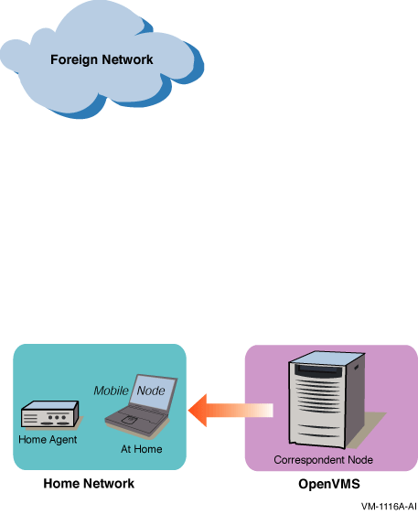
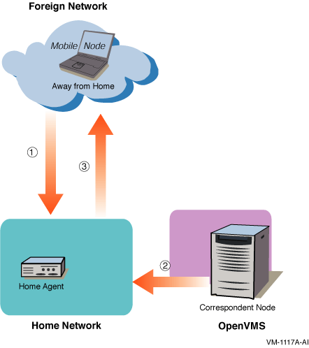
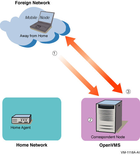
Figure 5-1, Figure 5-2, and Figure 5-3 show three scenarios that illustrate interactions among a correspondent node, home agent, and mobile node.
In Figure 5-1, the mobile node is on its home link (at home). Packets from the correspondent node that are addressed to the mobile node's home address are delivered through standard IP routing mechanisms.
Figure 5-1 Communication with Mobile Node at Home

In Figure 5-2, the mobile node has moved to a foreign link (away from home).
Figure 5-2 Communication with Mobile Node Away from Home--Part 1

On the foreign link, the following events occur:
In Figure 5-3, the mobile node has received the tunneled packets from the home agent.
Figure 5-3 Communication with Mobile Node Away from Home--Part 2

After the mobile node receives the tunneled packets, the following events occur:
When the mobile node back on its home link, the mobile node sends a binding update to the home agent and to the correspondent node to clear the bindings.
| Previous | Next | Contents | Index |