                                                +------------------+
                                                ! Cluster Synopsis !(1)
                                                +------------------+
(2)                              (3)
Cluster                         Match       Majorid   Minorid
-------                         -----       -------  ----------
MYCLU
DEFAULT_CLUSTER
DECC$SHR                        LESS/EQUAL        1           1
SYS$PUBLIC_VECTORS              EQUAL          9525   361572293
|
The items in the following list correspond to the numbered items in the preceding figure:
- Cluster Synopsis. For I64 systems, there are separate map sections titled Cluster Synopsis and Image Segment Synopsis. The Cluster Synopsis section on I64 does not contain segment information.
- Cluster. The Cluster column shows the names of the clusters created for and used by the linker, and the order in which they were processed. STARLET.OLB is an exception. It is on the default cluster but its processing is postponed after processing IMAGELIB.OLB. See Chapter 2 for more information on processing default libraries.
- Match, Majorid, and Minorid. The Match, Majorid, and Minorid columns show the GSMATCH criteria along with the major and minor version numbers, if this information is available. For more information, see the GSMATCH= option in Part 4.
5.2.3 Image Segment Synopsis
The Image Segment Synopsis section of the linker map file
(Example 5-3) lists the image segments created by the linker. The
image segments appear in the order in which the linker created them.
The order of the segments depends on the order of the clusters as shown
in the linker's image cluster synopsis (see Section 5.2.2). For I64
systems, segments of the shareable images which are included in the
link operation are not listed in the Image Segment Synopsis.
This section of the image map includes other information about the image segments, formatted in columns. To compare with the Alpha Image Section Synopsis map, see Section 9.2.3.
| Example 5-3 Image Segment Synopsis |
|---|
                                             +------------------------+
                                             ! Image Segment Synopsis !(1)
                                             +------------------------+
(2)    (3)                    (4)        (5)      (6)         (7)        (8)   (9)
(10)
Seg#  Cluster               Type      Pglts   Base Addr  Disk VBN  PFC  Protection  Attributes
----  -------               ----      -----   ---------  --------  ---  ----------  ----------
   0  MYCLU                 LOAD          1    00010000         2    0  READ WRITE
   1                        LOAD          1    00020000         0    0  READ WRITE  DEMAND ZERO
   2                        LOAD          1    00030000         3    0  READ ONLY   EXECUTABLE,SHARED
   3                        LOAD          1    00040000         4    0  READ ONLY   SHARED
   4                        LOAD          1    00050000         5    0  READ ONLY   [UNWIND]
   5  DEFAULT_CLUSTER       LOAD          1    00060000         6    0  READ ONLY   SHORT(11)
   6                        DYNAMIC       2  Q-00000000
                                               80000000         7    0  READ ONLY


              Key for special characters above
                +----------------------+
                !   Q  - Quad Value    !
                +----------------------+
|
The items in the following list correspond to the numbered items in the preceding figure:
- The Image Segment Synopsis section shows each segment as it was created.
- Seg#. The image's segment number, indicating
segments in the order the linker created them and used in image
relocations and image fixups that are applied to a segment by the image
activator.
Using the ANALYZE/IMAGE/SEGMENT=DYNAMIC command, you can format the dynamic segment, which includes the image relocations and fixups. The following extract of the ANALYZE shows how the segment numbers are used for image relocations:
Segment Offset Modified:   0000000000000050  imr$q_rela_offset
Image Relocation Type:             00000081  imr$l_type
Segment Being Modified:            00000003  imr$l_rela_seg
Image Relocation Addend:   0000000000000000  imr$q_addend
Symbol Segment Offset:     0000000000000000  imr$q_sym_offset
Symbol Segment Number:             00000000  imr$l_sym_seg
Virtual Address Affected:  0000000000040050
- Cluster. The name of each cluster the linker created, listed in the order in which the linker created them. For better readability, the cluster name is only shown for the first segment in the cluster.
- Type. The type of the segment, indicating if a segment will be in memory at run time (LOAD), or if the segment is used to activate the image (DYNAMIC).
- Pagelets. The length of each segment, expressed in pagelets (512-byte quantities).
- Base Address. The base address assigned to the segment. Note that all segments are relocatable, the image activator may relocate the base address.
- Disk VBN (virtual block number). The virtual block number of the image file on disk where the segment begins. The number 0 indicates that the segment is not in the image file. This is the case for demand-zero segments.
- Page fault cluster (PFC). The number of pagelets read into memory by the operating system when the initial page fault occurs for that segment. The number 0 indicates that the system parameter PFCDEFAULT determines this value, rather than the linker.
- Protection. The protection attributes of the
segment:
Keyword Meaning READ ONLY Indicates that the segment is protected against write access. READ WRITE Indicates that the segment allows both read and write access. - Attributes. A keyword phrase that
characterizes the settings of certain attributes of the image segment,
such as the attributes that affect paging.
The following table lists the keywords used by the linker to indicate these characteristics of an image segment:
Keyword Meaning DEMAND ZERO Indicates that the segment is a demand-zero segment. (For more information, see Section 3.4.4.) DZRO COMPRESSED Indicates that a segment had the trailing pagelets containing zeros compressed. (For more information, see Section 3.4.4.) EXECUTABLE Indicates that the segment contains code. PROTECTED Indicates that a segment at run time will be protected from user-mode and supervisor-mode write access. The image activator ensures the protection when the segment is in memory. (For more information, see Section 4.4) SHARED Indicates that a segment can be shared between several processes. SHORT Indicates a short data segment, data which is addressed with small offsets from the global pointer. (For more information, see Section 3.4.3.2) VECTOR Indicates that a segment contains privileged change-mode vectors or message vectors. [UNWIND] Indicates that a segment contains unwind information. Please note that UNWIND is not an attribute. The linker flags this segment for better readability because all other attributes may be identical to other segments. (For more information, see Section 3.2.1.5)
The linker may use more than one keyword to describe a segment. For example, to describe a segment that contains code, the linker uses the READ ONLY and EXECUTABLE keywords. - If the module was compiled with /TIE and the image is linked /NONATIVE_ONLY and if the image contains nonstandard signatures, a separate segment appears immediately after the short data segment that contains them.
5.2.4 Program Section Synopsis Section
The Program Section Synopsis section lists the sections that comprise
the image, along with information about the size of the section, its
starting- and ending-addresses, and its attributes. The Module Name
column in this map section lists the modules that contribute to each
section. Figure 5-1 shows the Program Section Synopsis.
Figure 5-1 Program Section Synopsis
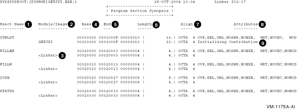
The items in the following list correspond to the numbered items in the preceding figure. There are two types of line entries: first type is a section entry (Psect Name); the second type are individual module contributions to that section (Module/Image).
- Psect Name. The name of each section in the image in ascending order of its base virtual address.
- Module/Image. The names of the modules that contribute to the section whose name appears on the line directly above in the Psect Name column. If a shareable image appears in this column, the section is overlaid onto the section in the shareable image.
- Base. The starting virtual address of the section or of a module that contributes to a section. If the section is overlaid onto a section in a shareable image, the virtual address is taken from the shareable image.
- End. The ending virtual address of the section or of a module that contributes to a section. If the section is overlaid onto a section in a shareable image, the virtual address is taken from the shareable image.
- Length. For the section entry line, the total length of the section in bytes; for the individual module contribution lines, the length of the individual contribution in bytes.
- Align. The type of alignment used for the
entire section or for an individual section contribution. The alignment
is expressed in two ways. In the first column, the alignment is
expressed using a predefined keyword, such as OCTA. In the second
column, the alignment is expressed as an integer that is the power of 2
that creates the alignment. For example, octaword alignment would be
expressed as the keyword OCTA and as the integer 4 (because
24 = 16). For more information on the effects of alignment
with the PSECT= option see Part 4.
If the linker does not support a keyword to express an alignment, it puts the text "2 **" in the column in which the keyword usually appears. When read with the integer in the second column, it expresses these alignments, such as 25 = 32. - Attributes. The attributes associated with the section. For a complete list of all the possible attributes, see Chapter 3.
- The linker indicates which modules made
initializations (if there were any) to sections which have the
attributes OVR, REL and GBL with the designation Initializing
Contribution.
If you get multiple initialization errors, the linker will have two or more sections marked with the designation Initializing Contribution, in order to help you debug an instance that has many contributors. - The linker contributes storage for common or relaxed ref/def symbols. It is marked with <Linker> under the Module/Image header. The section name is always named after the symbol. (In this example map the C module was compiled with the default switch /EXTERN=RELAXED, and the variables ITMLST, FILLEN, FILLIM and IOSB are relaxed ref/def symbols).
- The linker makes a contribution to the code section containing trampolines (instructions with larger branches within the same code segment) or code to branch to another segment (either inside or outside the image). It is marked with <Linker> under the Module/Image header.
If a routine is extracted from the default system library to resolve a symbolic reference, the Program Section Synopsis section in a full map contains information about the program sections comprising that routine. The Program Section Synopsis section in a default map does not. |
5.2.5 Symbol Cross-Reference Section
The Symbol Cross-Reference section is a superset of the Symbols By Name
section. It is produced in place of the Symbols By Name section when
you specify the /CROSS_REFERENCE qualifier. It lists all symbols
referenced in the image, along with the module in which they are
defined and with all the modules that reference them. Example 5-4
shows how the Symbol Cross-Reference Section formats this information.
| Example 5-4 Symbol Cross-Reference |
|---|
                                             +------------------------+
                                             ! Symbol Cross Reference !
                                             +------------------------+
(1)              (2)                 (3)                        (4)
Symbol          Value              Defined By                Referenced By ...
------          -----              ----------                -----------------
DECC$TXPRINTF   00000496-X(5)       DECC$SHR                  GETJPI
ELF$TFRADR      00060050-R      WK-GETJPI
FILLEN          00020000-R         GETJPI                    GETJPI
FILLM           00020010-R         GETJPI                    GETJPI
GETJPI (U)      00000000           <Linker Option>
INTERNAL_GETJPI 00060098-R         GETJPI
IOSB            00020020-R         GETJPI                    GETJPI
ITMLST          00010000-R         GETJPI
STATUS          00020030-R         GETJPI                    GETJPI
SYS$GETJPIW     0000009A-X         SYS$PUBLIC_VECTORS        GETJPI
|
The items in the following list correspond to the numbered items in the preceding figure:
- Symbol. The name of the global symbol.
- Value. The value of the global symbol, expressed in hexadecimal. The linker appends characters to the end of the symbol value to describe other characteristics of the symbol. For an explanation of these symbols, see Section 5.2.6.
- For I64 systems, the designation of an external symbol is always X (external). The linker can not know whether or not an external symbol is relocatable or not. As a result, the designation R (relocatable) can not be attached.
- Defined By. The name of the module in which the symbol is defined. For example, the symbol ITMLST is defined in the module named GETJPI.
- Referenced By... . The name or names of all the modules that contain at least one reference to the symbol.
5.2.6 Symbols By Value Section
The Symbols By Value section lists all the global symbols in the image
in ascending order by value. The linker formats the information into
columns. Example 5-5 shows the Symbols By Value map section.
| Example 5-5 Symbols by Value |
|---|
                                                +------------------+
                                                ! Symbols By Value !
                                                +------------------+
(1)              (2)
Value           Symbols...
-----           ----------
00000000        GETJPI (U)
0000009A      X-SYS$GETJPIW
00000496      X-DECC$TXPRINTF
00010000      R-ITMLST
00020000      R-FILLEN
00020010      R-FILLM
00020020      R-IOSB
00020030      R-STATUS
00060050      R-ELF$TFRADR
00060098      R-INTERNAL_GETJPI

              Key for special characters above(3)
                +----------------------+
                !   *  - Undefined     !
                !  (U) - Universal     !
                !   R  - Relocatable   !
                !   X  - External      !
                !   C  - Code Address  !
                !  WK  - Weak          !
                ! UxWk - Unix-Weak     !
                +----------------------+
|
The items in the following list correspond to the numbered items in the preceding figure:
- Value. The value of each global symbol, expressed in hexadecimal, in ascending numerical order.
- Symbols... . The names of the global symbols. If more than one symbol has the same value, the linker lists them on more than one line. The characters prefixed to the symbol names indicate other characteristics of the symbol, such as its scope.
- Keys for Special Characters. The keys for
special characters used in the Symbols column are defined as follows:
- On I64, the special character C appears for code address. When a function does not have a function descriptor assigned by the linker, its value is its code address.
- For I64 systems, universal symbols appear once with a suffix of
(U)
defined by <Linker Option> to indicate the external value, and
again, possibly with the prefix or suffix
R
, that indicates their internal value. The external value is the index
into the symbol vector. If you had a symbol vector with an alias name,
the alias name appears with the universal value, and the internal name
appears with the internal value.
For example, symbol_vector=(getjpi/internal_getjpi=procedure) yields:
   00000000        GETJPI (U)
   00050098      R-INTERNAL_GETJPI
Note that the OpenVMS Alpha prefixes and suffixes A and I (for Alias and Internal) are not used by I64. - WK designates a weak symbol.
- UxWk designates a UNIX-style weak symbol, which is similar to an OpenVMS weak symbol. However, more than one symbol with a UNIX-style weak definition can be processed when linking multiple modules without producing a multiple definitions error. UNIX-style weak symbols are currently produced by the C++ compiler. (For more information about symbol types, see Chapter 2.)
5.2.7 Image Synopsis Section
The Image Synopsis section contains miscellaneous information about the
image, such as its name and identification numbers, and a summary of
various attributes of the image, such as the number of files used to
build the image. Example 5-6 illustrates the format of this section
of a map file. The list following the example provides more information
about items in this section that are not self-explanatory.
| Example 5-6 Image Synopsis |
|---|
                                                 +----------------+
                                                 ! Image Synopsis !
                                                 +----------------+

Virtual memory allocated:(1)              00010000 0006FFFF 00060000 (393216. bytes, 768. pages)
64-Bit Virtual memory allocated:(2)       00000000 00000000 00000000
                                         80000000 80010000 00010000 (65536. bytes, 128. pages)
Stack size:(3)                                           0. pages
Image header virtual block limits:(4)             1.        1. (    1. block)
Image binary virtual block limits:(5)             2.        8. (    7. blocks)
Image name and identification:           GETJPI V1.0
Number of files:                                5.
Number of modules:                              3.
Number of program sections:                     8.
Number of global symbols:                    3364.
Number of cross references:                    17.
Number of image segments:                       7.
Transfer address from module:                GETJPI
User transfer FD address:(6)               00000000 00060050
User transfer code address:(7)             00000000 00030000
Initial FP mode:                        00000000 09800000 (IEEE DENORM_RESULTS)
Number of code references to shareable images:        2.
Image type:                             SHAREABLE. Global Section Match=EQUAL, Ident, Major=9533, Minor=3817251083
Reduced Floating Point model (RFP):     Image does not use RFP model
Map format:                             FULL WITH CROSS REFERENCE in file DISK$USER:[JOE]GETJPI.MAP;1
Estimated map length:                   443. blocks
|
The following item corresponds to the numbered item in Example 5-6:
- Virtual memory allocated. This line contains
the following information:
- The starting address of the image (base address)
- The ending address of the image
- The total size of the image, expressed in bytes, in hexadecimal radix
The numbers in parentheses at the end of the line indicate the total size of the image, expressed in bytes and in pagelets. Both these values are expressed in decimal. - 64-Bit Virtual memory allocated. The next two
lines contain information on the image portions in P2 space. The
virtual addresses are printed by column, in two rows, with the high
order digits in the first row. The values are as in the prceeding line:
the starting-address, the ending-address, the size.
Sections with the attribute ALLOC_64BIT are collected into P2 space (For more information on collecting sections and assigning virtual addresses see Chapter 3.) The linker usually places the image activator information (dynamic segment) into the 64-bit space. Therefore, for all I64 images, there usually is 64-bit virtual memory allocated. - Stack size.
- Image header virtual block limits. For I64 images, the header blocks contain the ELF header and the segment header table. This is usually one disk block.
- Image binary virtual block limits. For I64 images, the binary blocks contain the image binaries (the segments) and other sections, depending on the type of image. There can be traceback and debug information as well as symbol tables. Also, the section header table describing such sections is counted here.
- User transfer FD address. The virtual address of the function decriptor (FD) for the main entry. This is an address in the short data segment.
- User transfer code address. The virtual address of the first code instruction in the main entry. This is an address in an executable segment.
| Previous | Next | Contents | Index |