| Previous | Contents | Index |
The LAN Device Errors Data page (Figure 4-13) displays LAN device errors data.
Figure 4-13 LAN Device Errors Data
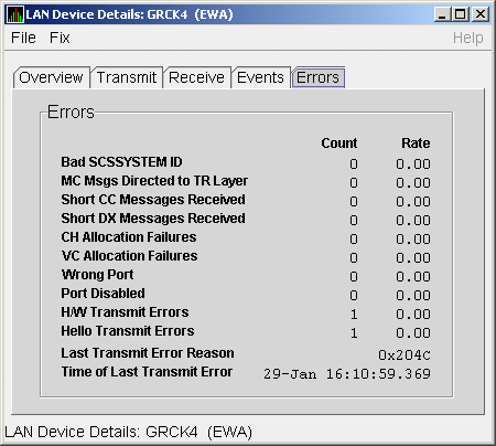
Table 4-13 describes the data displayed in Figure 4-13.
| Data | Description |
|---|---|
| Bad SCSSYSTEM ID | Received a packet with the wrong SCSSYSTEM ID in it. |
| MC Msgs Directed to TR Layer | Number of multicast packets directed to the NISCA Transport layer. |
| Short CC Messages Received | Number of packets received that were too short to contain a NISCA channel control header. |
| Short DX Messages Received | Number of packets received that were too short to contain a NISCA DX header. |
| CH Allocation Failures | Number of times the system failed to allocate memory for use as a channel structure in response to a packet received by this LAN device. |
| VC Allocation Failures | Number of times the system failed to allocate memory for use as a VC structure in response to a packet received by this LAN device. |
| Wrong Port | Number of packets addressed to the wrong NISCA address. |
| Port Disabled | Number of packets discarded because the LAN device was disabled. |
| H/W Transmit Errors | Number of local hardware transmit errors. |
| Hello Transmit Errors | Number of transmit errors during HELLOs. |
| Last Transmit Error Reason | Reason for last transmit error. |
| Time of Last Transmit Error | Time of last transmit error: date and time. |
To display LAN path (channel) detail data, right-click a LAN channel summary data item on the Cluster Summary page (Figure 4-6). The Availability Manager displays a shortcut menu with the options shown in Figure 4-8.
To display LAN channel details, select the Channel Details... item on
the menu. After a brief delay, a LAN Channel Overview Data page
(Figure 4-14) is displayed. A series of tabs at the top of this page
indicate additional channel pages that you can display.
4.3.3.1 LAN Channel Overview Data
The LAN Channel Overview Data page (Figure 4-14) displays general channel data, including the state, status, and total errors of the channel.
Figure 4-14 LAN Channel Overview Data
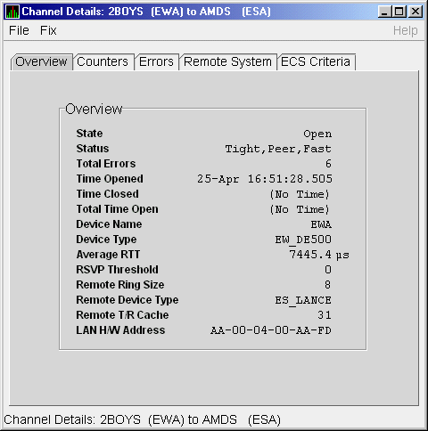
Table 4-14 describes the data displayed in Figure 4-14.
| Data | Description |
|---|---|
| State | Channel's current state: OPEN, PATH, or CLOSED. |
| Status | Channel status. |
| Total Errors | Sum of channel's error counters. |
| Time Opened | Last time that this channel had a path to a remote system. |
| Time Closed | Last time that this channel was closed. |
| Total Time Open | Total time that this channel has been open. |
| Device Name | Local LAN device name. |
| Device Type | Local LAN device type. |
| Average RTT | Average of measured round-trip time. |
| RSVP Threshold | Number of packets before requesting that the remote node immediately return an acknowledgment. |
| Remote Ring Size | Number of entries in the remote LAN device. |
| Remote Device Type | Remote LAN device type. |
| Remote T/R Cache | Number of out-of-order packets that the remote transmit/receive resequencing cache can buffer. |
| LAN H/W Address | LAN device's hardware address. |
The LAN Channel Counters Data page (Figure 4-15) displays path counters data, including ECS transitions as well as messages and bytes sent.
Figure 4-15 LAN Channel Counters Data
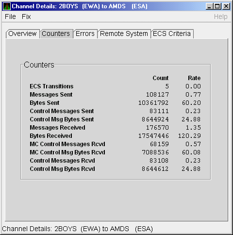
Table 4-15 describes the data displayed in Figure 4-15.
| Data | Description |
|---|---|
| ECS Transitions | Number of times this channel has been in and out of the equivalent channel set (ECS). |
| Messages Sent | Number of packets sent over this channel, including control packets. |
| Bytes Sent | Number of bytes transmitted on this channel, including control packets. |
| Control Messages Sent | Number of control packets sent, not including multicast packets. |
| Control Msg Bytes Sent | Number of control packet bytes sent, not including multicast packets. |
| Messages Received | Number of packets received by this channel. |
| Bytes Received | Number of bytes in packets received by this channel. |
| MC Control Messages Rcvd | Number of multicast control packets received. |
| MC Control Msg Bytes Rcvd | Number of multicast control packets bytes received. |
| Control Messages Rcvd | Number of control packets received. |
| Control Msg Bytes Rcvd | Number of control packet bytes received. |
The LAN Channel Errors Data page (Figure 4-16) displays LAN channel errors data.
Figure 4-16 LAN Channel Errors Data
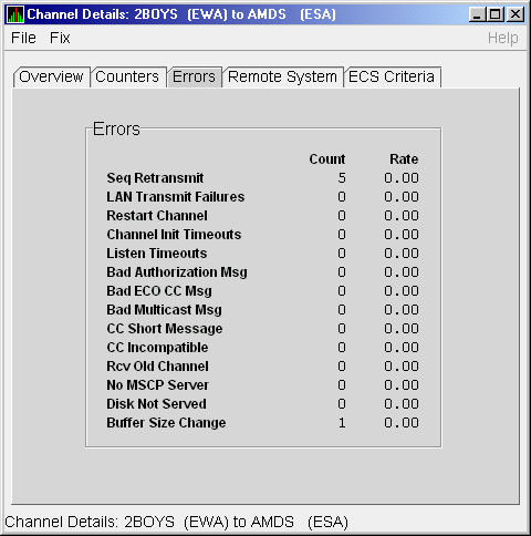
Table 4-16 describes the data displayed in Figure 4-16.
| Data | Description |
|---|---|
| Seq Retransmit | Number of times a sequenced VC packet sent on this channel was retransmitted, and the channel was penalized for the lost packet. |
| LAN Transmit Failures | Number of times the local LAN device reported a failure to transmit a packet, and channel was penalized for the lost packet. |
| Restart Channel | Close/restart because of channel control packet was received indicating the other end closed the channel and is restarting the channel handshake. |
| Channel Init Timeouts | Channel initialization handshake timeout. |
| Listen Timeouts | No packets of any kind, including HELLOs, were received in LISTEN_TIMEOUT seconds. |
| Bad Authorization Msg | Received a CC (channel control) packet with a bad authorization field. |
| Bad ECO CC Msg | Received a CC packet with an incompatible NISCA protocol ECO rev. field value. |
| Bad Multicast Msg | Received a bad multicast CC packet. |
| CC Short Packet | Received a CC packet that was too short. |
| CC Incompatible | Received a CC packet that was incompatible with existing channels for this virtual circuit. |
| Rcv Old Channel | Received a packet from an old instance of a channel. |
| No MSCP Server | No MSCP server available to respond to a received channel control solicit service packet asking this node to boot serve another node. |
| Disk Not Served | Disk is not served by this system. |
| Buffer Size Change | Change in buffer size. |
The LAN Channel Remote System Data page (Figure 4-17) displays LAN path remote system data.
Figure 4-17 LAN Channel Remote System Data
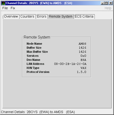
Table 4-17 describes the data displayed in Figure 4-17.
| Data | Description |
|---|---|
| Node Name | Node name of remote system. |
| Buffer Size | Buffer size (largest possible buffer size) of remote system. |
| Max Buffer Size | Current upper bound on buffer size usable on this channel. |
| Services | NISCA services supported on this channel. |
| Dev Name | Name of the remote LAN device. |
| LAN Address | Remote hardware address. |
| H/W Type | Hardware type of remote node. |
| Protocol Version | NISCA protocol version of remote system. |
The LAN Channel ECS Criteria Data page (Figure 4-18) displays equivalent channel set criteria data.
Figure 4-18 LAN Channel ECS Criteria Data
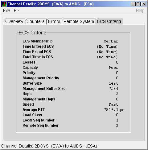
Table 4-18 describes the data displayed in Figure 4-18.
| Data | Description |
|---|---|
| ECS Membership | ECS membership status; that is, Member or Nonmember. |
| Time Entered ECS | Last time this channel entered the ECS. |
| Time Exited ECS | Last time this channel exited the ECS. |
| Total Time in ECS | Total time this channel was in the ECS. |
| Losses | Value representing channel's recent packet loss history. |
| Capacity | Channel's capacity rating based on evaluating its priority, buffer size, and hops values relative to the current ECS criteria. Values are: Ungraded, Peer, Inferior, Superior. |
| Priority | Channel's current priority for ECS calculations; it is the sum of the management priorities assigned to the local LAN device and to the channel. |
| Management Priority | Dynamic management-assigned priority. |
| Buffer Size | Negotiated maximum common buffer size: the smaller of local and remote BUS$ limits on block data field sizes. |
| Management Buffer Size | Maximum block data field size assigned by dynamic management. |
| Hops | Number of switches or bridges for this channel. |
| Management Hops | Management-supplied hops or media packet storage equivalent. |
| Speed | Classification of channel's delay relative to that of the lowest delay of any ECS member. |
| Average RTT | Average measured round-trip time. |
| Load Class | Lesser of the local and remote LAN device load class values. |
| Local Seq Number | Sequence number of the local channel. |
| Remote Seq Number | Sequence number of the remote channel. |
The Network Interconnect for System Communications Architecture (NISCA) is the transport protocol responsible for carrying packets such as disk I/Os and lock packets across Ethernet and FDDI LANs to other nodes in the cluster.
The LAN virtual circuit details (NISCA) pages show detailed information about the LAN Ethernet or FDDI connection between two nodes. The Availability Manager displays one window for each LAN virtual circuit. This page is intended primarily to provide real-time aids for diagnosing LAN-related cluster communications problems. HP OpenVMS Cluster Systems describes the parameters shown on these pages and tells how to diagnose LAN-related cluster problems.
The LAN Virtual Circuit Details pages provide the same information as the SCACP command SHOW VC and as the following OpenVMS System Dump Analyzer (SDA) commands: PE VC and SHOW PORTS/VC=VC_ remote-node-name. In these commands, remote-node-name is the SCS name of another node in the cluster.
SDA defines VC_remote-node-name and performs the first SHOW PORTS action after SDA is started. Thus, the /CH and /VC options are valid only with the second and subsequent SHOW PORT commands.
You can display LAN virtual circuit details data by double-clicking a "LAN Virtual Circuit Summary" data row or by right-clicking a menu on the Cluster Summary page (Figure 4-6). After a brief delay, a LAN VC Transmit Data page (Figure 4-19) is displayed. The tabs at the top of the page indicate additional pages that you can display.
The data items displayed depend on the type of virtual circuit.
Currently, this feature is available only for LAN virtual circuits.
4.3.4.1 LAN VC Transmit Data
Transmit data is information about the transmission of data packets, including the numbers of packets and bytes sent. Figure 4-19 is an example of a LAN VC Transmit Data page.
Figure 4-19 LAN VC Transmit Data
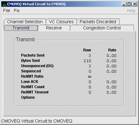
Table 4-19 describes the data displayed in Figure 4-19.
| Data | Description |
|---|---|
| Packets Sent | (Raw) count and rate of packets transmitted through the virtual circuit to the remote node, including both sequenced and unsequenced (channel control) packets and lone acknowledgments. |
| Bytes Sent | (Raw) count and rate of bytes transmitted through the virtual circuit. |
| Unsequenced (DG) | (Raw) count and rate of the number of unsequenced packets that are transmitted. |
| Sequenced | (Raw) count and rate of sequenced packets transmitted. Sequenced packets are guaranteed to be delivered. |
| ReXMT Ratio | Ratio of the total number of sequenced packets sent to the current retransmission count. |
| Lone ACK | (Raw) count and rate of packets sent solely for the purpose of acknowledging receipt of one or more packets. |
| ReXMT Count | Number of packets retransmitted. Retransmission occurs when the local node does not receive an acknowledgment for a transmitted packet within a predetermined timeout interval. |
| ReXMT Timeout | Number of retransmission timeouts that have occurred. |
| Options |
Transmit options enabled:
CKSM---packet checksumming |
Receive data is information about the receipt of data packets. Figure 4-20 is an example of a LAN VC Receive Data page.
Figure 4-20 LAN VC Receive Data
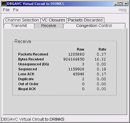
Table 4-20 describes the data displayed in Figure 4-20.
| Data | Description |
|---|---|
| Packets Received | (Raw) count and rate of packets received on the virtual circuit from the remote node, including both sequenced and unsequenced---that is, datagram packets and lone acknowledgments. |
| Bytes Received | (Raw) count and rate of bytes received in packets over the virtual circuit. |
| Unsequenced (DG) | (Raw) count and rate of unsequenced---datagram---packets received. |
| Sequenced | (Raw) count and rate of sequenced packets received. |
| Lone ACK | (Raw) count and rate of lone acknowledgments received. |
| Duplicate | Number of duplicated packets received by this system. Duplicates occur when the sending node retransmits a packet, and both the original and the retransmitted packets are received. |
| Out of Order | Number of packets received out of order by this system. |
| Illegal ACK | Number of illegal acknowledgments received---that is, acknowledgments of an out-of-range sequence number. |
LAN VC congestion control data is information about LAN traffic. The values indicate the number of packets that can be sent to the remote node before receiving an acknowledgment and the retransmission timeout.
Figure 4-21 is an example of a LAN VC Congestion Control Data page. An item that is dimmed indicates that the current version of OpenVMS does not support that item.
Figure 4-21 LAN VC Congestion Control Data
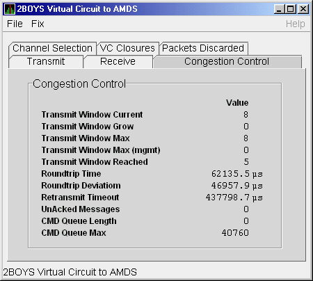
Table 4-21 describes the data displayed in Figure 4-21.
| Data | Description |
|---|---|
| Transmit Window Current | Current value of the transmit window (or pipe quota). After a timeout, the pipe quota is reset to 1 to decrease network path congestion. The pipe quota is allowed to increase as quickly as acknowledgments are received. |
| Transmit Window Grow | The slow growth threshold. The size at which the increase rate of the window is slowed to avoid congestion on the network again. |
| Transmit Window Max | Maximum transmit window size currently allowed for the virtual circuit based on channel and remote PEDRIVER receive cache limitations. |
| Transmit Window Max (mgmt) | Management override to calculated value for Maximum Transmit Window size. N/A on systems prior to Version 2.0. |
| Transmit Window Reached | Number of times the entire transmit window was full. If this number is small compared with the number of sequenced packets transmitted, then either the local node is not sending large bursts of data to the remote node, or acknowledging packets are being received so promptly that the window limit is never reached. |
| Roundtrip Time | Average round-trip time, in microseconds, for a packet to be sent and acknowledged. |
| Roundtrip Deviation | Average deviation, in microseconds, of the round-trip time. |
| Retransmit Timeout | Value, in microseconds, used to determine packet retransmission timeout. If a packet does not receive either an acknowledging or a responding packet, the packet is assumed to be lost and will be resent. |
| UnAcked Packets | Current number of unacknowledged packets. |
| CMD Queue Length | Current length of the virtual circuit's command queue. |
| CMD Queue Max | Maximum number of commands in the virtual circuit's command queue so far. |
| Previous | Next | Contents | Index |