 |
HP OpenVMS systems documentation |
| Previous | Contents | Index |
The configuration in Figure 8-7 incorporates the following strategies, which are critical to its success:
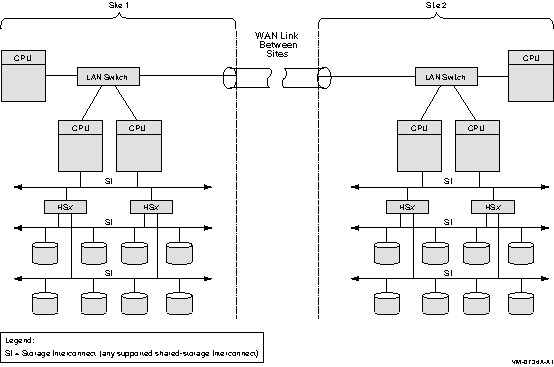
Multiple-site OpenVMS Cluster configurations contain nodes that are located at geographically separated sites. Depending on the technology used, the distances between sites can be as great as 150 miles. FDDI, asynchronous transfer mode (ATM), and DS3 are used to connect these separated sites to form one large cluster. Available from most common telephone service carriers, DS3 and ATM services provide long-distance, point-to-point communications for multiple-site clusters.
Figure 8-8 shows a typical configuration for a multiple-site OpenVMS Cluster system. Figure 8-8 is followed by an analysis of the configuration that includes:
Figure 8-8 Multiple-Site OpenVMS Cluster Configuration Connected by WAN Link

Although Figure 8-8 does not show all possible configuration combinations, a multiple-site OpenVMS Cluster can include:
The benefits of a multiple-site OpenVMS Cluster system include the following:
Reference: For additional information about
multiple-site clusters, see HP OpenVMS Cluster Systems.
8.12 Disaster-Tolerant OpenVMS Cluster Configurations
Disaster-tolerant OpenVMS Cluster configurations make use of Volume Shadowing for OpenVMS, high-speed networks, and specialized management software.
Disaster-tolerant OpenVMS Cluster configurations enable systems at two different geographic sites to be combined into a single, manageable OpenVMS Cluster system. Like the multiple-site cluster discussed in the previous section, these physically separate data centers are connected by FDDI or by a combination of FDDI and ATM, T3, or E3.
The OpenVMS disaster-tolerant product was formerly named the Business Recovery Server (BRS). BRS has been subsumed by a services offering named Disaster Tolerant Cluster Services, which is a system management and software service package. For more information about Disaster Tolerant Cluster Services, contact your HP Services representative.
There are many ways to configure a CI (cluster interconnect) OpenVMS
Cluster system. This chapter describes how to configure CI OpenVMS
Clusters to maximize both availability and performance. This is done by
presenting a series of configuration examples of increasing complexity,
followed by a comparative analysis of each example. These
configurations illustrate basic techniques that can be scaled upward to
meet the availability, I/O performance, and storage connectivity needs
of very large clusters.
9.1 CI Components
The CI is a radial bus through which OpenVMS Cluster systems communicate with each other and with storage. The CI consists of the following components:
Availability and performance can both be increased by adding components. Components added for availability need to be configured so that a redundant component is available to assume the work being performed by a failed component. Components added for performance need to be configured so that the additional components can work in parallel with other components.
Frequently, you need to maximize both availability and performance. The
techniques presented here are intended to help achieve these dual goals.
9.2 Configuration Assumptions
The configurations shown here are based on the following assumptions:
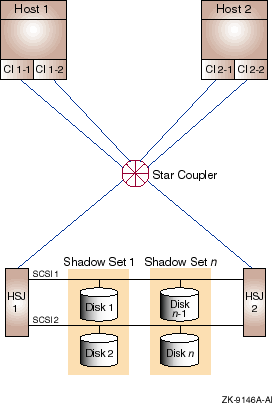
Configuration 1, shown in Figure 9-1, provides no single point of failure. Its I/O performance is limited by the bandwidth of the star coupler.
Figure 9-1 Redundant HSJs and Host CI Adapters Connected to Same CI (Configuration 1)

9.3.1 Components
The CI configuration shown in Figure 9-1 has the following
components:
| Part | Description |
|---|---|
| Host 1, Host 2 |
Dual CI capable OpenVMS Alpha or VAX hosts.
Rationale: Either host can fail and the system can continue. The full performance of both hosts is available for application use under normal conditions. |
| CI 1-1,CI 1-2, CI 2-1,CI 2-2 |
Dual CI adapters on each host.
Rationale: Either of a host's CI adapters can fail and the host will retain CI connectivity to the other host and to the HSJ storage controllers. |
| Star Coupler |
One star coupler cabinet containing two independent path hubs. The star
coupler is redundantly connected to the CI host adapters and HSJ
storage controllers by a transmit/receive cable pair per path.
Rationale: Either of the path hubs or an attached cable could fail and the other CI path would continue to provide full CI connectivity. When both paths are available, their combined bandwidth is usable for host-to-host and host-to-storage controller data transfer. |
| HSJ 1, HSJ 2 |
Dual HSJ storage controllers in a single StorageWorks cabinet.
Rationale: Either storage controller can fail and the other controller can assume control of all disks by means of the SCSI buses shared between the two HSJs. When both controllers are available, each can be assigned to serve a portion of the disks. Thus, both controllers can contribute their I/O-per-second and bandwidth capacity to the cluster. |
| SCSI 1, SCSI 2 |
Shared SCSI buses between HSJ pairs.
Rationale: Provide access to each disk on a shared SCSI from either HSJ storage controller. This effectively dual ports the disks on that bus. |
| Disk 1, Disk 2, . . . Disk n-1, Disk n |
Critical disks are dual ported between HSJ pairs by shared SCSI buses.
Rationale: Either HSJ can fail, and the other HSJ will assume control of the disks that the failed HSJ was controlling. |
| Shadow Set 1 through Shadow Set n |
Essential disks are shadowed by another disk that is connected on a
different shared SCSI.
Rationale: A disk or the SCSI bus to which it is connected, or both, can fail, and the other shadow set member will still be available. When both disks are available, their combined READ I/O capacity and READ data bandwidth capacity are available to the cluster. |
This configuration offers the following advantages:
This configuration has the following disadvantages:
This configuration incorporates the following strategies:
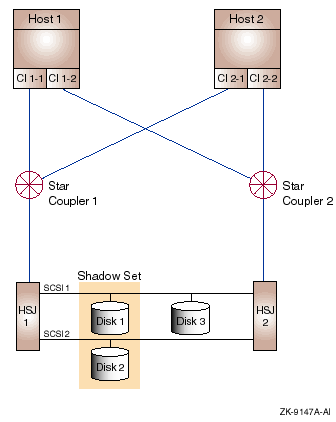
The configuration illustrated in Figure 9-2 with redundant HSJs, host CI adapters, and CIs provides no electrical single point of failure. Its two star couplers provide increased I/O performance and availability over configuration 1.
Figure 9-2 Redundant HSJs and Host CI Adapters Connected to Redundant CIs (Configuration 2)

Configuration 2 has the following components:
| Part | Description |
|---|---|
| Host 1, Host 2 |
Dual CI capable OpenVMS Alpha or VAX hosts.
Rationale: Either host can fail and the system can continue to run. The full performance of both hosts is available for application use under normal conditions. |
| CI 1-1,CI 1-2, CI 2-1, CI 2-2 |
Dual CI adapters on each host. Adapter CI 1-
n is Host 1's CI adapter connected to CI
n, and so on.
Rationale: Either of a host's CI adapters can fail, and the host will retain CI connectivity to the other host and to the HSJ storage controllers. Each CI adapter on a host is connected to a different star coupler. In the absence of failures, the full data bandwidth and I/O-per-second capacity of both CI adapters is available to the host. |
| Star Coupler 1, Star Coupler 2 |
Two star couplers, each consisting of two independent path hub
sections. Each star coupler is redundantly connected to the CI host
adapters and HSJ storage controllers by a transmit/receive cable pair
per path.
Rationale: Any of the path hubs or an attached cable could fail and the other CI path would continue to provide full connectivity for that CI. Loss of a path affects only the bandwidth available to the storage controller and host adapters connected to the failed path. When all paths are available, the combined bandwidth of both CIs is usable. |
| HSJ 1, HSJ 2 |
Dual HSJ storage controllers in a single StorageWorks cabinet.
Rationale: Either storage controller can fail and the other controller can control any disks the failed controller was handling by means of the SCSI buses shared between the two HSJs. When both controllers are available, each can be assigned to serve a subset of the disks. Thus, both controllers can contribute their I/O-per-second and bandwidth capacity to the cluster. |
| SCSI 1, SCSI 2 |
Shared SCSI buses connected between HSJ pairs.
Rationale: Either of the shared SCSI buses could fail and access would still be provided from the HSJ storage controllers to each disk by means of the remaining shared SCSI bus. This effectively dual ports the disks on that bus. |
| Disk 1, Disk 2, . . . Disk n-1, Disk n |
Critical disks are dual ported between HSJ pairs by shared SCSI buses.
Rationale: Either HSJ can fail and the other HSJ will assume control of the disks the failed HSJ was controlling. |
| Shadow Set 1 through Shadow Set n |
Essential disks are shadowed by another disk that is connected on a
different shared SCSI.
Rationale: A disk or the SCSI bus to which it is connected, or both, can fail and the other shadow set member will still be available. When both disks are available, both can provide their READ I/O capacity and their READ data bandwidth capacity to the cluster. |
Configuration 2 offers all the advantages of Configuration 1 plus the following advantages:
Configuration 2 has the following disadvantages:
Configuration 2 provides configuration 1 strategies, plus:
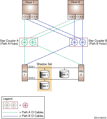
The availability of a CI configuration can be further improved by physically separating the path A and path B CI cables and their associated path hubs. This significantly reduces the probability of a mechanical accident or other localized damage destroying both paths of a CI. This configuration is shown in Figure 9-3.
Figure 9-3 Redundant Components and Path-Separated Star Couplers (Configuration 3)

Configuration 3 is electrically identical to configuration 2. However, the path A and path B cables are physically separate for both CIs. The path A cables for both CI 1 and CI 2 are routed together to star coupler cabinet A, but are connected to different CI path hubs in that cabinet.
Similarly, the path B cables for both CIs go to different CI path hubs in star coupler cabinet B. The path-specific star coupler cabinets and associated path cables should be separated as much as possible. For example, the star coupler cabinets could be installed on opposite sides of a computer room, and the CI cables could be routed so that path A and path B cables follow different paths.
The path separation technique illustrated for configuration 3 (Figure 9-3) can also be applied to configuration 1 (Figure 9-1). In this case, each star coupler cabinet would have only one path hub. The CI's path A cables would go to the path hub in Star Coupler A. Similarly, the path B cables would go to Star Coupler B. |
The CI OpenVMS Cluster configuration shown in Figure 9-3 has the following components:
| Part | Description |
|---|---|
| Host 1, Host 2 |
Dual CI capable OpenVMS Alpha or VAX hosts.
Rationale: Either host can fail and the system can continue. The full performance of both hosts is available for application use under normal conditions. |
| CI 1-1,CI 1-2, CI 2-1, CI 2-2 |
Dual CI adapters on each host. Adapter CI 1-
n is Host 1's CI adapter connected to CI
n, and so on.
Rationale: Either host's CI adapters can fail and the host will retain CI connectivity to the other host and to the HSJ storage controllers. Each CI adapter on a host is connected to a different star coupler. In the absence of failures, the full data bandwidth and I/O-per-second capacity of both CI adapters is available to the host. |
| Star Coupler A (Path A Hubs), Star Coupler B (Path B Hubs) |
Two CI star couplers, each comprising two independent path hubs. Star
Coupler A's path hubs are connected to path A cables for both CIs, and
Star Coupler B's path hubs are connected to path B cables for both CIs.
Rationale: Mechanical or other localized damage to a star coupler or an attached cable would probably not affect the other CI paths. The other paths and star coupler would continue to provide full connectivity for both CIs. Loss of a path affects only the bandwidth available to the storage controllers and host adapters connected to the failed path. When all paths are available, the combined bandwidth of both CIs is usable. |
| Path A CI Cables, Path B CI Cables | Each path's hub is connected to the CI host adapters and HSJ storage controllers by a transmit/receive cable pair per path. The path A cables of both CIs are routed together, but their routing differs from the routing of the path B cables. |
| HSJ 1, HSJ 2 |
Dual HSJ storage controllers in a single StorageWorks cabinet.
Rationale: Either storage controller can fail and the other controller can control any disks the failed controller was handling by means of the SCSI buses shared between the two HSJs. When both controllers are available, each can be assigned to serve a subset of the disks. Thus, both controllers can contribute their I/O-per-second and bandwidth capacity to the cluster. |
| SCSI 1, SCSI 2 |
Shared SCSI buses connected between HSJ pairs.
Rationale: Provide access to each disk on a shared SCSI bus from either HSJ storage controller. This effectively dual ports the disks on that bus. |
| Disk 1, Disk 2, . . . Disk n-1, Disk n |
Critical disks are dual ported between HSJ pairs by shared SCSI buses.
Rationale: Either HSJ can fail and the other HSJ will assume control of the disks that the failed HSJ was controlling. |
| Shadow Set 1 through Shadow Set n |
Essential disks are shadowed by another disk that is connected on a
different shared SCSI.
Rationale: A disk, or the SCSI bus to which it is connected, or both, can fail and the other shadow set member will still be available. When both disks are available, their combined READ I/O-per-second capacity and READ data bandwidth capacity is available to the cluster. |
| Previous | Next | Contents | Index |