|
|
HP OpenVMS systems documentation |
| Previous | Contents | Index |
Body regions can do anything that does not invalidate the state of the stack frames and preserved registers as recorded for that region. A body region must obey the following restrictions:
At every point in a body region, the unwind descriptors identify a single location where a valid value for SP, PSP, AR.PFS, PC, and each preserved register can be found. The body region must not modify a register or memory location while the unwind descriptors indicate that one of these items (SP, PSP, AR.PFS, PC, preserved register) is stored there.
The locations of these saved values (SP, PSP, AR.PFS, PC, preserved
registers) generally remain constant throughout the body region in
locations specified in the prologue descriptor records. However, when
this is not the case, the unwind descriptors described in Table A-13
can be used to mark changes in the unwind state within a body region. A
body region can restore AR.PFS, RP, and any preserved registers.
A.3.4 Conventions for Epilogues
The memory stack pointer (SP) is typically restored just before executing a return branch. In a normal epilogue at the end of a body region, the instruction that restores the previous SP value can be anywhere within a few instructions of the end of the region; the unwind descriptor format provides a place to record the exact location of this instruction. If the procedure has a memory stack frame and has return instructions in the middle of the body, the procedure must be divided into separate body regions, each ending at the point of each return instruction.
The unwinder does not need a specific epilogue region that is distinct
from the body region.
A.3.5 Conventions for the Spill Area in the Memory Stack Frame
The spill area for preserved general, floating-point, and branch registers is near the base of the stack frame, in a continuous range ending (by default) at the base of the stack frame plus 16 bytes (PSP+16). In other words, the 16-byte scratch area in the caller's stack frame is normally included in the spill area. If the scratch area is needed to save register parameters for a variable-argument list procedure, the spill area can be moved so that it ends at a lower address, but the ending address must be a fixed location relative to the base of the frame (PSP).
Locations in the spill area are reserved for each preserved general, floating-point, and branch register that is saved anywhere within the procedure (including shrink-wrapped regions). Locations are allocated, from low address to high, for (in order) general registers, then branch registers, and then floating-point registers. Registers are saved in numerical order, lower-numbered registers at lower addresses. The spill area must end at a 16-byte boundary, so that all the floating-point spill locations are 16-byte aligned.
It is not required that all registers preserved in the spill area be consecutive from each register file. If, for example, R4 and R7 are preserved, but R5 and R6 are not, space is allocated only for R4 and R7.
Code may need to spill scratch registers in addition to preserved registers. There are no conventions for spilling scratch registers, because they do not need to be recovered during a stack unwind. To make the best use of the User NaT collection register, general register spills should be adjacent to the preserved general register spill area.
Normally, the unwinder expects to find the NaT bits for the preserved registers in the User NaT collection register, AR.UNAT. If the total spill area for general registers (scratch and preserved registers combined) exceeds 64 quadwords, it is necessary to save the User NaT collection register in order to spill up to an additional 64 general registers. In this overflow situation, two or more NaT collections are managed by swapping them in and out of the single collection register. The NaT collection that contains the NaT bits for the preserved registers is called the primary UNaT collection, and the unwinder must know where to find these bits. In procedures where the NaT collection register is multiplexed, the location of the primary UNaT collection is recorded in the unwind information.
If the primary UNaT collection is saved, then the location of the primary UNaT value must be recorded, as well as when that value is restored. The only way to do the latter is by using one of the general unwind descriptors found in Section A.4.1.1.
The unwinder must take special note of the time at which the primary UNaT is restored. In the case of an unwind after the primary UNaT restore, the unwinder must not attempt to redundantly reperform any fills that preceded that restore because the applicable UNaT state will have been lost.
In this regard, the UNaT restore operation is analogous to a stack restore operation. It forms a barrier after which saved state has been lost. As a result, some or all of the state restoration cannot be reperformed. |
The condition handling mechanism uses the following data structures:
Every procedure (except some leaf procedures) has one entry in this table. (If the compiler has generated more than one noncontiguous region of code for a procedure, there is one entry in this table for each region.) Each unwind table entry points to an information block that contains the following data structures:
Given a PC value, the dispatcher and unwinder both use the unwind table to locate an unwind entry for a procedure. The unwinder also uses the unwind descriptor list to unwind the stack from any point in the procedure.
The operating system-specific data area contains information about a routine as a whole that is not otherwise expressible using the unwind descriptors, independent of whether the routine has a condition handler.
The language-specific data area contains information specific to the
condition handler that uses it. The address of the language-specific
data area is passed to the condition handler whenever the condition
handler is invoked by the dispatcher.
A.4.1 Unwind Table and Unwind Information Block
The unwind table is a sequence of sorted unwind table entries. Unwind table entries contain three fields, as illustrated in Figure A-1; each field is a 64-bit quadword. The first two fields define the starting and ending addresses of the region, respectively. The third field points to a variable-size information block that contains the unwind descriptor list and language-specific data area. The ending address is the address of the first bundle beyond the end of the procedure. Because these values are all segment-relative offsets rather than absolute addresses, they do not require run-time relocations. The unwind table entries are sorted by the region start address. The shaded area in the figure represents the language-specific data area.
Figure A-1 Unwind Table and Unwind Information Block
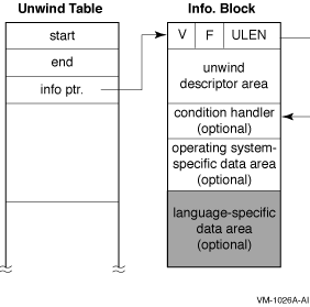
Note that a leaf procedure may have no unwind table entry (see Section A.5).
The unwind table and the unwind information block must each be aligned at an 8-byte boundary. Within the information block, the condition handler pointer must also be aligned at an 8-byte boundary.
The first quadword of the information block consists of the following fields:
#define UNW_IVMS_MODE(x) (((x) >> 44) & 0x3L) |
For OpenVMS I64, the value of UNW_IVMS_MODE field must be 2 or 3. Otherwise, exception handling behaviour is undefined. |
These fields may be accessed with the following macros:
| #define UNW_LENGTH(x) | ((x) & 0x00000000ffffffffL) |
| #define UNW_FLAG_UHANDLER(x) | ((x) & 0x0000000200000000L) |
| #define UNW_FLAG_EHANDLER(x) | ((x) & 0x0000000100000000L) |
| #define UNW_FLAG_OSMASK | 0x0000f00000000000L |
| #define UNW_FLAG_MASK | 0x0000ffff00000000L |
| #define UNW_VER(x) | ((x) >> 48) |
| Field | Bit Position | Description | ||||||||||
|---|---|---|---|---|---|---|---|---|---|---|---|---|
| EHANDLER | <0> | Set if there is an exception-processing handler established (for this region). (Note that for OpenVMS I64, the EHANDLER and UHANDLER flags are both set or both not set.) | ||||||||||
| UHANDLER | <1> | Set if there is an exception cleanup (second/unwind pass) handler established. (Note that for OpenVMS I64, the EHANDLER and UHANDLER flags are both set or both not set.) | ||||||||||
| UNUSED | <11:2> | Reserved | ||||||||||
| UNW_IVMS_MODE | <13:12> |
|
||||||||||
| OS_SPECIFIC_FLAGS | <15:14> | Reserved; must be zero. |
The unwind descriptor area contains a contiguous sequence of records describing the unwind regions in the procedure. Each group of records begins with a region header record that identifies the type and length of the region. The region header record is followed by any number of descriptor records that supply additional unwind information about the region.
Unwind descriptor records are divided into three categories:
This section describes the record types in each of these categories, lists rules for using unwind descriptor records, and explains how the records must be processed.
The information is encoded in variable-length records with a record type and one or more additional fields. The length of each record is implicit from the record type and its fields. All records are an integral number of bytes in length. In the descriptor record tables in the next three sections, the third column lists the format of each record type. These record formats are described in Appendix B.
Because the unwind descriptor area must be a multiple of 8 bytes, the
last unwind descriptor must be followed by zero bytes as necessary to
pad the area to an 8-byte boundary. These zero bytes will be
interpreted as prologue region header records, specifying a zero-length
prologue region, and serve as no-ops.
A.4.1.2 Region Header Records
The region header records are listed in Table A-2.
| Record Type | Fields | Format | Description |
|---|---|---|---|
| BODY | RLEN | R1/R3 | Defines a body region. |
| PROLOGUE | RLEN | R1/R3 | Defines a general prologue region. |
| PROLOGUE_GR | RLEN, MASK, GRSAVE | R2 | Defines a prologue region with a mask of saved registers, and a set of general registers used for saving preserved registers. |
The fields in these records are used as follows:
The entry state for a region matches the exit state of the preceding region, except for body regions that contain a COPY_STATE descriptor record, which is described in Table A-12.
The exit state of a region is determined as follows:
This section lists the descriptor records that can be used to describe prologue regions. In addition, the descriptor records described in Section A.4.1.5 can also be used. In the absence of any descriptor records or information in the region header record, a prologue region is assumed to create no memory stack frame and save no registers. Descriptors need be supplied only to override these defaults.
Table A-3 describes the descriptor records that are used to record information about the stack frame and the state of the previous stack pointer (PSP).
| Record Type | Fields | Format | Description |
|---|---|---|---|
| MEM_STACK_F | T, SIZE | P7 | Specifies a fixed-size memory stack frame, when SP is modified, and size of frame. |
| MEM_STACK_V | T | P7 | Specifies a variable-size memory stack frame, and when PSP is saved. |
| PSP_GR | GR | P3 | Specifies the general register where PSP is saved. |
| PSP_SPREL | SPOFF | P7 | Specifies (as an SP-relative offset) the memory location where PSP is saved. |
The fields in these records are used as follows:
Table A-4 describes the descriptor records that are used to record the state of the return pointer (RP).
| Record Type | Fields | Format | Description |
|---|---|---|---|
| RP_WHEN | T | P7 | Specifies when RP is saved. |
| RP_GR | GR | P3 | Specifies the general register where RP is saved. |
| RP_BR | BR | P3 | Specifies the alternate branch register used as return pointer. |
| RP_PSPREL | PSPOFF | P7 | Specifies (as a PSP-relative offset) the memory location where RP is saved. |
| RP_SPREL | SPOFF | P8 | Specifies (as an SP-relative offset) the memory location where RP is saved. |
The fields in these records are used as follows:
Table A-5 describes the descriptor records that are used to record the state of the previous function state register (AR.PFS).
| Record Type | Fields | Format | Description |
|---|---|---|---|
| PFS_WHEN | T | P7 | Specifies when AR.PFS is saved. |
| PFS_GR | GR | P3 | Specifies general register where AR.PFS is saved. |
| PFS_PSPREL | PSPOFF | P7 | Specifies (as a PSP-relative offset) the memory location where AR.PFS is saved. |
| PFS_SPREL | SPOFF | P8 | Specifies (as an SP-relative offset) the memory location where AR.PFS is saved. |
Table A-6 describes the descriptor records that are used to record the state of the preserved predicate registers.
| Record Type | Fields | Format | Description |
|---|---|---|---|
| PREDS_WHEN | T | P7 | Specifies when the predicate registers are saved. |
| PREDS_GR | GR | P3 | Specifies the general register where predicate registers are saved. |
| PREDS_PSPREL | PSPOFF | P7 | Specifies (as a PSP-relative offset) memory location where predicate registers are saved. |
| PREDS_SPREL | SPOFF | P8 | Specifies (as an SP-relative offset) memory location where predicate registers are saved. |
Table A-7 describes the descriptor records that are used to record the state of the preserved general registers, floating-point registers, and branch registers.
| Record Type | Fields | Format | Description |
|---|---|---|---|
| FR_MEM | RMASK | P6 | Specifies (as a bit mask) which preserved floating-point registers are spilled to memory by this prologue. |
| FRGR_MEM | GRMASK, FRMASK | P5 | Specifies (as a bit mask) which preserved general and floating-point registers are spilled to memory by this prologue. |
| GR_GR | GRMASK, GR | P9 | Specifies (as a bit mask) which preserved general registers are saved in other general registers, and the general register where first preserved general register is saved. |
| GR_MEM | RMASK | P6 | Specifies (as a bit mask) which preserved general registers are spilled to memory by this prologue. |
| BR_MEM | BRMASK | P1 | Specifies (as a bit mask) which preserved branch registers are spilled to memory by this prologue. |
| BR_GR | BRMASK, GR | P2 | Specifies (as a bit mask) which preserved branch registers are saved in general registers by this prologue, and the general register where first branch register is saved. |
| SPILL_BASE | PSPOFF | P7 | Specifies (as a PSP-relative offset) end of (first byte following the) spill area in memory stack frame. |
| SPILL_MASK | IMASK | P4 | Specifies (as a bit mask) when preserved registers are spilled. |
| Previous | Next | Contents | Index |