 |
HP OpenVMS systems documentation |
| Previous | Contents | Index |
Predicate registers are single-bit-wide registers used for controlling the execution of predicated instructions. There are 64, onebit predicate registers (P0P63) that control conditional execution of instructions and conditional branches. The first register, P0, is read only and always reads true (1). The results of instructions that write to P0 are discarded.
This standard defines the usage of the OpenVMS predicate registers as listed in Table 18-6.
| Register | Class | Usage |
|---|---|---|
| P0 | Constant | Always 1. |
| P1-P5 | Preserved | Can be used for any predicate value that needs to be preserved across a procedure call. A procedure using one of the preserved predicate registers must save and restore the caller's original contents. |
| P6-P13 | Scratch | Can be used within a procedure as a scratch register. |
| P14-P15 | Volatile | Cannot be used to pass information between procedures, either as input or output. |
| P16-P63 | Preserved | Rotating registers. |
Branch registers are used for making indirect branches. There are 8, 64bit branch registers (B0B7) that are used to specify the target addresses of indirect branches.
This standard defines the usage of the OpenVMS branch registers as listed in Table 18-7.
| Register | Class | Usage |
|---|---|---|
| B0 | Scratch | Contains the return address on entry to a procedure; otherwise a scratch register. |
| B1-B5 | Preserved | Can be used for branch target addresses that need to be preserved across a procedure call. |
| B6-B7 | Volatile | May not be used to pass information between procedures, either as input or output. |
A stack is a last-in/first-out (LIFO) temporary storage area that the system allocates for every user process. The system keeps information about each routine call in the current image on the call stack. Then, each time you call a routine, the system creates a structure on the stack, defined as the stack frame.
Stack frames and call frames are synonymous. A call frame for each
procedure has a specified format containing pointers and control
information necessary in the transfer of control between procedures of
a call chain. Stack frames (call frames) of standard calling procedures
differ across Alpha, VAX, and I64 systems.
18.2.1 Stack Procedure Usage for VAX
Figure 18-1 shows the format of the stack frame created for the called procedure by the CALLG or CALLS instruction. The stack frame (pointed to by SP) is in the context of the current procedure, and call frames (pointed to by FP) are the preserved stack frames of other active procedures in the call chain. The stack frame (call frame) for each procedure in the chain contains the following:
Figure 18-1 Call Frame Generated by CALLG and CALLS Instructions
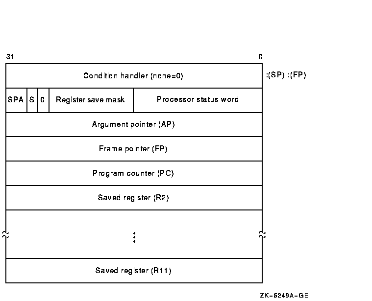
The contents of the stack located at addresses following the call frame belong to the calling program; they should not be read or written by the called procedure, except as specified in the argument list. The contents of the stack located at addresses lower than the call frame (at FP) belong to interrupt and exception routines; they are modified continually and unpredictably.
The called procedure allocates local storage by subtracting the
required number of bytes from the stack provided on entry. This local
storage is freed automatically by the RET instruction.
18.2.1.1 Calling Sequence
At the option of the calling procedure, the called procedure is invoked using the CALLG or CALLS instruction, as follows:
     CALLG    arglst, procedure
     CALLS    argcnt, procedure
|
CALLS pushes the argument count argcnt onto the stack as a longword and sets the argument pointer, AP, to the top of the stack. The complete sequence using CALLS follows:
     push     argn
     .
     .
     .
     push     arg1
     CALLS    #n, procedure
|
If the called procedure returns control to the calling procedure, control must return to the instruction immediately following the CALLG or CALLS instruction. Skip returns and GOTO returns are allowed only during stack unwind operations.
The called procedure returns control to the calling procedure by executing the return instruction (RET).
Note that when a routine completes execution, the system uses the FP in
the call frame of the current procedure to locate the frame of the
previous procedure. The system then removes the stack frame of the
current procedure from the stack.
18.2.2 Stack Procedure Usage for Alpha
On Alpha systems, when a standard procedure is called, the language compiler creates a stack frame for that procedure. The stack format of a stack frame procedure consists of a fixed part (the size of which is known at compile time) and an optional variable part. There are two basic types of stack frames:
Figure 18-2 illustrates the format of the stack frame for a procedure with a fixed amount of stack. The SP register is the stack base pointer for a fixed-size stack. In this case, R29 (FP) typically contains the address of the procedure descriptor for the current procedure.
The optional parts of the stack frame are created only as required by the particular procedure. As shown in Figure 18-2, the field names within brackets are optional fields. The fixed temporary locations are optional sections of any stack frame that contain language-specific locations required by the procedure context of some high-level languages.
The register save area is a set of consecutive quadwords in which registers that are saved and restored by the current procedure are stored. The register save area (RSA) begins at the location pointed to by the RSA offset. The contents of the return address register (R26) are always saved in the first register field (SAVED_RETURN) of the register save area.
Use of the arguments passed in memory appending the end of the frame is described in Section 18.4. For more detail concerning the fixed-size stack frame, see the HP OpenVMS Calling Standard.
Figure 18-2 Fixed-Size Stack Frame Format
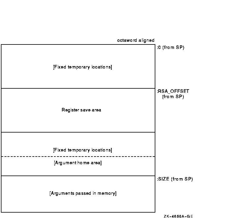
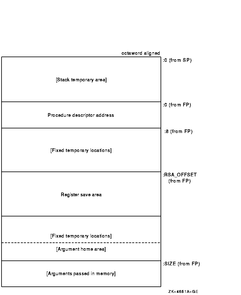
Figure 18-3 illustrates the format of the stack frame for procedures with a varying amount of stack when PDSC$V_BASE_REG_IS_FP is 1. In this case, R29 (FP) contains the address that points to the base of the stack frame on the stack. This frame-base quadword location contains the address of the current procedure's descriptor.
The optional parts of the stack frame are created as required by the particular procedure. As shown in Figure 18-3, field names within brackets are optional fields. The fixed temporary locations are optional sections of any stack frame that contain language-specific locations required by the procedure context of some high-level languages.
A compiler can use the stack temporary area pointed to by the SP base register for fixed local variables, such as constant-sized data items and program state, as well as for dynamically sized local variables. The stack temporary area may also be used for dynamically sized items with a limited lifetime, for example, a dynamically sized function result or string concatenation that cannot be directly stored in a target variable. When a procedure uses this area, the compiler must keep track of its base and reset SP to the base to reclaim storage used by temporaries.
The register save area is a set of consecutive quadwords in which registers saved and restored by the current procedure are stored. The register save area (RSA) begins at the location pointed to by the offset PDSC$W_RSA_OFFSET. The contents of the return address register (R26) is always saved in the first register field (SAVED_RETURN) of the register save area.
Use of the arguments passed in memory appending the end of the frame is described in Section 18.4. For more detail concerning the variable-size stack frame, see the HP OpenVMS Calling Standard.
Figure 18-3 Variable-Size Stack Frame Format
The I64 general registers are organized as a logically infinite set of stack frames that are allocated from a finite pool of physical registers.
Registers R0 through R31 are called global or static registers and are not part of the stacked registers. The stacked registers are numbered R32 up to a userconfigurable maximum of R127. A called procedure specifies the size of its new stack frame using the alloc instruction. The procedure can use this instruction to allocate up to 96 registers per frame shared among input, output, and local values. When a call is made, the output registers of the calling procedure are overlapped with the input registers of the called procedure, thereby allowing parameters to be passed with no register copying or spilling. The hardware renames physical registers so that the stacked registers are always referenced in a procedure starting at R32.
Management of the register stack is handled by a hardware mechanism
called the Register Stack Engine (RSE). The RSE moves the contents of
physical registers between the general register file and memory without
explicit program intervention. This provides a programming model that
looks like an unlimited physical register stack to compilers; however,
saving and restoring of registers by the RSE may be costly, so
compilers should still attempt to minimize register usage.
18.2.3.1 Procedure Types
This calling standard defines the following basic types of procedures:
Unlike an Alpha null frame procedure (see the HP OpenVMS Calling Standard), an I64 null frame procedure does not execute in the context of its caller because the I64 call instruction (br.call) changes the register set so that only the caller's output registers are accessible in the called routine. The caller's input and local registers cannot be accessed at all. The call instruction also changes the previous frame state (PFS) of the I64 processor. |
A compiler may choose which type of procedure to generate based on the requirements of the procedure in question. A calling procedure does not need to know what type of procedure it is calling.
Every memory stack procedure or register stack procedure must have an associated unwind description (see the HP OpenVMS Calling Standard) that describes what type of procedure it is and other procedure characteristics. A null frame procedure may also have an associated unwind description. (If not, a default description applies.) This data structure is used to interpret the call stack at any given point in a thread's execution. It is typically built at compile time and usually is not accessed at run time except to support exception processing or other rarely executed code.
Read access to unwind descriptions is provided through the procedural interfaces described in the HP OpenVMS Calling Standard.
An unwind description for a procedure is provided for the following reasons:
The memory stack is used for local dynamic storage, spilled registers, and parameter passing. It is organized as a stack of procedure frames, beginning with the main program's frame at the base of the stack, and continuing towards the top of the stack with nested procedure calls. At the top of the stack is the frame for the currently active procedure. (There may be some system-dependent frames at the base of the stack, prior to the main program's frame, but an application program may not make any assumptions about them.)
The memory stack begins at an address determined by the operating system, and grows towards lower addresses in memory. The stack pointer register (SP) always points to the lowest address in the current, topmost frame on the stack.
Each procedure creates its frame on entry by subtracting its frame size from the stack pointer, and removes its frame from the stack on exit by restoring the previous value of SP (usually by adding its frame size, but a procedure may save the original value of SP when its frame size varies).
Because the register stack is also used for the same purposes as the
memory stack, not all procedures need a memory stack frame. However,
every nonleaf procedure must save at least its return link and the
previous frame marker, either on the register stack or on the memory
stack. This ensures that there is an invocation context for every
nonleaf procedure on one or both of the stacks.
18.2.3.3 Procedure Frames
A memory stack procedure frame consists of five regions, as illustrated in Figure 18-4.
Figure 18-4 Procedure Frame
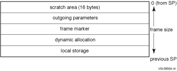
These regions are:
Whenever control is transferred to another procedure, the stack pointer must be octaword aligned; at other times there is no stack alignment requirement. (A side effect of this is that the in-memory portion of the argument list will start on an octaword boundary.) During a procedure invocation, the SP can never be set to a value higher than the SP at entry to that procedure invocation.
A stack pointer that is not octaword aligned is valid only in a variable-sized frame because the unwind descriptor (MEM_STACK_F, see the HP OpenVMS Calling Standard) for a fixed-size frame specifies the size in 16-byte units. |
An application may not write to memory addresses lower than the stack pointer, because this memory area may be written to asynchronously (for example, as a result of exception processing).
Most procedures are expected to have a fixed-size frame, and the conventions are biased in favor of this. A procedure with a fixed-size frame may reference all regions of the frame with a compile-time constant offset relative to the stack pointer. Compilers should determine the total size required for each region, and pad the local storage area to make the total frame size a multiple of 16 bytes. The procedure can then create the frame by subtracting an immediate constant from the stack pointer in the prologue, and remove the frame by adding the same immediate constant to the stack pointer in the epilogue.
If a procedure has a variable-size frame (for example, a C routine that calls the alloca builtin), it should make a copy of SP to serve as a frame pointer before subtracting the initial frame size from the stack pointer. The procedure can then restore the previous value of the stack pointer in the epilogue without regard for how much dynamic storage has been allocated within the frame. It can also use the frame pointer to access the local storage region, because offsets from SP will vary.
A frame pointer is not required if both of the following conditions are true:
To expand a stack frame dynamically, the scratch area, outgoing parameters, and frame marker regions (which are always located relative to the current stack pointer), must be relocated to the new top of stack. If the scratch area and outgoing parameter area are both clear of any live values, there is no actual work involved in relocating these areas. For procedures with dynamically sized frames, it is recommended that the previous stack pointer value be stored in a local stacked general register instead of the frame marker, so that the frame marker is also empty. If the previous stack pointer is stored in the frame marker, the code must take care to ensure that the stack is always unwindable while the stack is being expanded (see the HP OpenVMS Calling Standard).
Other issues depend on the compiler and the code being compiled. The
standard calling sequence does not define a maximum stack frame size,
nor does it restrict how a language system uses any stack frame region
beyond those purposes described here. For example, the outgoing
parameter region can be used as scratch storage whenever it is not
needed for passing parameters.
18.2.3.4 Register Stack
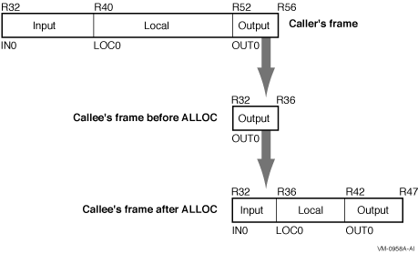
General registers R32 through R127 form a register stack that is automatically managed across procedure calls and returns. Each procedure frame on the register stack is divided into two dynamically sized regions: one for input parameters and local variables, and one for output parameters.
On a procedure call, the registers are automatically renamed by the hardware so that the caller's output registers form the base of the register stack frame of the callee. On return, the registers are restored to the previous state, so that the input and local registers are preserved across the call.
The ALLOC instruction is used at the beginning of a procedure to allocate the input, local, and output regions; the sizes of these regions are supplied as immediate operands. A procedure is not required to issue an ALLOC instruction if it does not need to store any values in its register stack frame. It may write to the first N stacked registers, where N is the value of the argument count passed in the argument information (AI) register (see Section 18.5.6). It may not write to any other stack register without first issuing an ALLOC instruction.
Figure 18-5 illustrates the operation of the register stack across an example procedure call. In this example, the caller allocates eight input, twelve local, and four output registers; the callee allocates four input, six local, and five output registers with the following instruction:
ALLOC R36=rspfs, 4, 6, 5, 0 |
The actual registers to which the stacking registers are physically
mapped are not directly addressable by the application software.
18.2.3.4.1 Input and Local Registers
The hardware makes no distinction between input and local registers. The caller's output registers automatically become the callee's register stack frame on a procedure call, with all registers initially allocated as output registers. An ALLOC instruction may increase or decrease the total size of the register stack frame, and may adjust the boundary between the input and local region and the output region.
The software conventions specify that up to eight general registers are used for parameter passing. Any registers in the input and local region beyond those eight may be allocated for use as preserved locals. Floating-point parameters may produce holes in the parameter list that is passed in the general registers; those unused input registers may also be used for preserved locals.
The caller's output registers do not need to be preserved for the caller. Once an input parameter is no longer needed, or has been copied elsewhere, that register may be reused for any other purpose within the procedure.
Figure 18-5 Operation of the Register Stack
| Previous | Next | Contents | Index |